
A series circuit is an electrical configuration where components are connected along a single path, meaning the current must flow through each device sequentially to complete the loop. If any single component in this arrangement fails or is disconnected, the entire circuit is broken, and current flow ceases immediately across the whole system. Understanding this fundamental design is essential for grasping how basic electronics and residential wiring systems function in everyday environments.
Key Takeaways
- Check for broken wires if a device stops working, as a single gap halts the entire circuit.
- Remember that total voltage in a series circuit is the sum of the individual voltage drops across each resistor.
- Note that the current remains constant at every point within the loop regardless of the number of components.
- Use series connections for low-voltage applications like small decorative light strings or specific sensor arrays.
- Avoid using series circuits for household appliances, as one failure would disable every device in the loop.
What Is A Series Circuit?
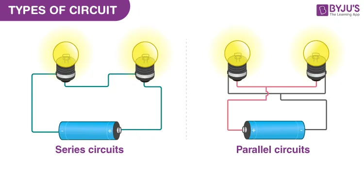
In basic terms, a series circuit is a closed loop where the current has only one path to follow. Unlike parallel circuits, which offer multiple routes, this configuration forces the electrical charge to traverse every component one after another.
If you have three light bulbs in a series, the electrons must pass through the first, then the second, and finally the third to return to the power source. Because there’s only one path, the total resistance of the circuit is simply the sum of all individual resistances added together.
How Current Behaves In Series
In a series circuit, the current is identical at every point. This happens because charge can’t be created or destroyed within the loop; therefore, the amount of current leaving the battery must be the same as the current flowing through each resistor or lamp. If you measure the amperage at the start, middle, or end of the string, you’ll find the same value. This constant current flow is a defining characteristic that distinguishes series designs from more complex parallel branches.
Understanding Voltage In Series
While current stays the same, voltage behaves differently. The total voltage provided by the source is distributed among the components based on their individual resistance. Each component experiences a “voltage drop,” which is the difference in electrical potential before and after the current passes through it.
| Component Property | Behavior in Series Circuit |
|---|---|
| Current (Amps) | Constant throughout the entire loop |
| Total Voltage | Sum of individual voltage drops |
| Total Resistance | Sum of all individual resistances |
| Path Availability | Single path only |
Why Use A Series Arrangement?

Engineers and designers choose series circuits when they need to control multiple components with a single switch. For example, a series setup is often used in basic safety interlock systems where a machine should only run if every door or panel is securely closed. If one switch opens, the circuit breaks, and the machine shuts down immediately. This provides a simple, reliable way to monitor multiple conditions simultaneously using a single control line.
Limitations Of Series Circuits
The primary drawback of a series circuit is its lack of redundancy. If one light bulb burns out in a series string, it creates an open circuit, and every other bulb in that string goes dark.
This makes troubleshooting difficult because you have to test each component individually to find the faulty one. Furthermore, adding more components increases the total circuit resistance, which reduces the overall current and makes each subsequent device dimmer or less efficient than the one before it.
Troubleshooting Your Series Circuit
When a device in your series circuit fails, you must isolate the point of failure systematically. Begin by checking the power source to ensure it’s providing the expected voltage. If the source is functional, move to each component in the loop.
- Inspect physical connections for loose wires or corrosion.
- Use a multimeter to measure the voltage across each component.
- Look for burned-out filaments or damaged insulation.
- Test each switch to ensure it’s fully closed.
Comparison: Series vs Parallel
Understanding the difference between these two configurations helps you choose the right design for your project. A parallel circuit allows current to divide into multiple branches, ensuring that if one component fails, the others remain powered. In contrast, a series circuit forces the current through all parts, making it better for specific control logic but worse for reliability.
| Feature | Series Circuit | Parallel Circuit |
|---|---|---|
| Wiring Path | Single path | Multiple branches |
| Component Failure | Disables everything | Only affects one branch |
| Voltage | Shared/Divided | Constant across branches |
| Complexity | Simpler to build | More complex wiring |
Prototyping With Series Components
When building a prototype, you might use common components to test your logic before moving to a permanent board. Always ensure your power supply matches the total voltage requirements of your series string. If you connect too many components, the voltage drop may prevent the devices from operating correctly.
- Resistors: Used to limit current in the loop.
- LEDs: Must be compatible with the current flow.
- Switches: Act as the gatekeepers for the circuit.
- Breadboards: Useful for quick, non-permanent testing.
Safety Considerations For Circuits

Warning: Always disconnect the power supply before modifying any circuit configuration to avoid electrical shock or component damage. Even low-voltage series circuits can produce enough heat to melt insulation if a short occurs. When working with batteries, ensure they aren’t damaged, as a shorted series circuit can cause them to overheat rapidly. Always use appropriate circuit protection devices like fuses to mitigate risks during testing phases.
Frequently Asked Questions
Does current change in a series circuit?
No, the current remains constant throughout a series circuit. Because there’s only one path for the electrons to travel, the amount of charge passing through any given point in the loop is identical to the amount passing through any other point. If you measure the amperage at the beginning or the end of the series, the reading will be the same.
Why do all lights go out in series?
All lights go out because a series circuit is a single, continuous loop. If one component, such as a light bulb, breaks or is removed, it creates an “open circuit” or a physical gap in the path. Since the electricity can’t jump across this gap, the flow of current stops entirely, causing every other component in the series to lose power simultaneously.
How do I calculate total resistance?
Calculating the total resistance in a series circuit is straightforward: you simply add the individual resistance values of every component together. If you have three resistors with values of 10 ohms, 20 ohms, and 30 ohms, the total resistance for the entire circuit is 60 ohms. This additive property is a fundamental rule for designing series-based electrical systems.
Can I mix series and parallel?
Yes, you can combine these configurations to create what is known as a series-parallel or “combination” circuit. This allows you to gain the benefits of both designs. For example, you might place several groups of parallel components in a series with each other. This is common in complex electronics where you need specific voltage drops while maintaining reliability in certain branches of the system.
Is my house wired in series?
No, residential homes aren’t wired in series. Household circuits are wired in parallel to ensure that every outlet and light fixture receives the full voltage from the panel. If your home were wired in series, turning on a toaster would affect the brightness of your lights, and a single dead bulb would cause a total power outage for the entire house.
Conclusion
To gain a deeper understanding of how these principles apply to your own electrical projects, obtain a basic digital multimeter and practice measuring the voltage drops across a series of small, low-voltage resistors. Starting with safe, battery-powered components is the best way to visualize these concepts in practice. Experimenting with these simple loops will provide the hands-on experience necessary to troubleshoot more complex systems with confidence and precision.
