
A start stop circuit is a common electrical configuration that uses two push buttons to control a motor, where a magnetic contactor keeps the machine running until the stop button cuts the power. This setup is the standard way to safely manage heavy equipment in factories, pumps, and conveyor systems because it prevents a machine from restarting on its own if the electricity goes out and comes back on.
Essential parts of a start stop circuit
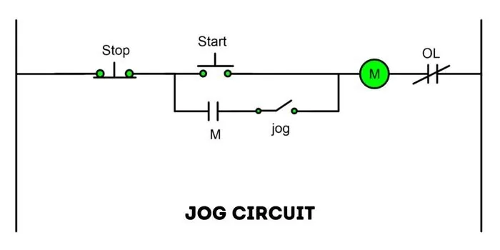
These systems rely on specific electrical parts to function reliably. You should check the labels on your own equipment to confirm the voltage and amperage ratings, as these values change depending on the size of the motor you’re running.
| Part or input | What it does | What you notice when it goes wrong |
|---|---|---|
| Start button | Sends power to the coil | Motor doesn’t turn on |
| Stop button | Breaks the circuit path | Motor won’t shut off |
| Magnetic contactor | Switches the high power | Clicking sound but no motor |
| Overload relay | Protects motor from heat | Motor trips and stops often |
| Control wires | Carries the signal current | Loose wires cause intermittent faults |
Always verify the contactor’s coil voltage before replacement. A 24V coil installed in a 120V circuit will burn out instantly, while a 120V coil in a 24V circuit will fail to pull the contacts closed.
If your motor trips frequently, check the overload relay dial. It should be set exactly to the full-load amperage listed on the motor nameplate. Setting this higher than the rated value risks a catastrophic motor burnout, while setting it lower triggers nuisance trips that halt production.
Inspect your control wiring annually for signs of oxidation. If you find a loose terminal, replace the crimped lug entirely rather than tightening the screw, as heat cycles often degrade the metal’s integrity. Have a technician verify continuity across your stop button; if there’s an issue, they should replace the contact block to prevent ghost signals.
How to wire a basic motor control system
Wiring this circuit requires careful attention to the path of the electricity. If you aren’t comfortable working with high-voltage equipment, you should hire a licensed electrician to perform the installation.
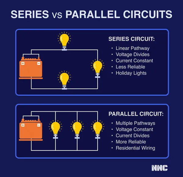
A common mistake here is wiring the holding contact in series instead of parallel. That forces you to hold the start button down for the motor to keep running.
- Connect the power source to the normally closed contact on the stop button.
- Run a wire from the other side of the stop button to the start button.
- Connect the start button to the input side of the magnetic contactor coil.
- Add a parallel wire from the start button to the holding contact. Use the auxiliary normally open contact mounted directly on the contactor body.
- Link the holding contact output back to the coil input side.
- Install an overload relay between the contactor and the motor terminals. Without it, a stalled rotor will burn out the windings before the breaker trips.
- Test the circuit by pressing start to engage the contactor magnets.
- Verify the stop button releases the contactor immediately when pressed.
Why wiring matters for machine safety

The core of this system is the holding contact, often called a seal-in circuit. When you press the start button, it sends a brief pulse of electricity to the magnetic contactor coil. The contactor pulls in, closing its main contacts to run the motor, but it also closes its own auxiliary contact.
This auxiliary contact creates a new path for electricity to flow around the start button. Because of this, you can release the button and the motor stays running. If the power fails, the magnetic field in the coil collapses, and the contactor drops out.
The stop button is always wired in series with the entire control path. It’s a normally closed switch, meaning it allows current to flow until you physically break the connection. If the stop button fails or the wire breaks, the circuit loses its power path, and the motor simply won’t start.
This is a deliberate safety feature defined by OSHA machine guarding standards to ensure that operators always have a reliable way to kill power to moving parts. The biggest mistake people make is using the wrong wire gauge for the control circuit, which leads to overheating or voltage drops that prevent the contactor from closing fully.
What you can change and what you can’t
You have control over the button placement and the wire paths, but the internal mechanics of the contactor are fixed by the manufacturer. Only make changes if you have the proper tools and training to avoid electrical shock.
Things you control
- The physical location of the buttons.
- The length of wires between components.
- The type of enclosure used for safety.
- The gauge of the control wiring used.
Fixed design limits
- The voltage rating of the internal coil.
- The maximum amperage the contactor handles.
- The physical spring tension of the contacts.
Getting more out of your control system
Practical maintenance keeps these circuits running for years without trouble. You should check for loose terminal screws based on frequency of use and the manufacturer’s recommendations in the owner’s manual. Vibration from the motor can loosen connections over time.
If you notice the contactor humming loudly, it often means dirt or debris is stuck between the metal laminations of the magnet. This prevents it from closing flush. You should never use oil or grease on these contacts. It attracts dust and causes electrical arcing.
If the contactor tips are pitted or burned, replace the entire contactor assembly rather than trying to file them down. Filing removes the silver alloy surface that resists welding under load. A filed contact will fuse shut within weeks, leaving your motor running when you need it stopped.
If you run a motor that draws a high current, have a technician ensure your overload relay is set correctly for the specific motor nameplate rating to prevent premature motor failure.
Watch the ambient temperature where your panel sits. Thermal overload relays rely on internal heaters bending a bimetallic strip. In an unventilated enclosure near a furnace, that strip bends early and trips your circuit before the motor actually reaches its safe operating limit.
Related guides
Frequently asked questions
Can I wire a start stop circuit without a contactor?
No, you can’t safely run a large motor without a contactor because standard push buttons aren’t built to handle the high current required by a motor. A contactor acts as a heavy-duty switch that keeps the high-voltage electricity separate from the low-voltage button circuit you touch.
How long do magnetic contactors usually last?
Most contactors last for millions of cycles, but the exact lifespan depends on the electrical load and the frequency of starts. You can find the expected mechanical life rating printed on the side of the contactor housing or in the manufacturer’s technical manual provided with the part.
Is it safe to replace a contactor myself?
It’s safe to replace a contactor only if you have turned off the main power at the breaker and verified it with a voltage tester. Capacitors can hold a charge, so never touch the internal wiring until you’re certain the power is fully disconnected.
What happens if I press both buttons at once?
The motor won’t start because the stop button is wired in series before the start button in the control loop. Pressing the stop button breaks the entire path, so no electricity can reach the contactor coil regardless of the start button’s position.
Does the wire color matter for this circuit?
Yes, wire colors help you identify the circuit type quickly, though local building codes determine the exact standard. In many industrial settings, red is used for control power, black for high-voltage lines, and green or bare copper for the essential safety ground connection.
How do I know if my contactor is the right size?
You must match the contactor’s horsepower or full-load amperage rating to the motor’s specific nameplate data. Check the motor label for the full-load amps and compare that figure to the contactor’s specification sheet to ensure it handles your motor’s power demand safely.
Conclusion
Building these controls is a great way to improve your electrical skills, but always double-check your connections before flipping the main breaker. If you’re feeling confident, try adding an emergency stop button to your layout for extra safety. You’ll find that these reliable circuits aren’t just useful; they’re essential for any workshop.
