
In the world of power electronics, managing the flow of electricity from a source to a load is rarely as simple as a direct connection. Engineers frequently encounter scenarios where the available input voltage doesn’t match the requirements of the device being powered. This is exactly why professionals and hobbyists investigate buck and buck boost converters what are they and their working to ensure efficient power delivery. These circuits allow for the precise regulation of voltage, ensuring that sensitive electronics receive a stable supply regardless of fluctuations in the power source.
Key Takeaways
- Use a buck converter when you need to step down a higher input voltage to a lower output voltage.
- Employ a buck-boost converter if your source voltage might be higher, lower, or equal to the desired output.
- Efficiency in these circuits relies on high-speed switching components like MOSFETs to minimize energy loss as heat.
- Inductors act as temporary storage reservoirs for energy, smoothing out the rapid pulses created by the switch.
- Always match your converter’s current rating to the peak demand of your load to prevent thermal failure.
Understanding the Buck Converter
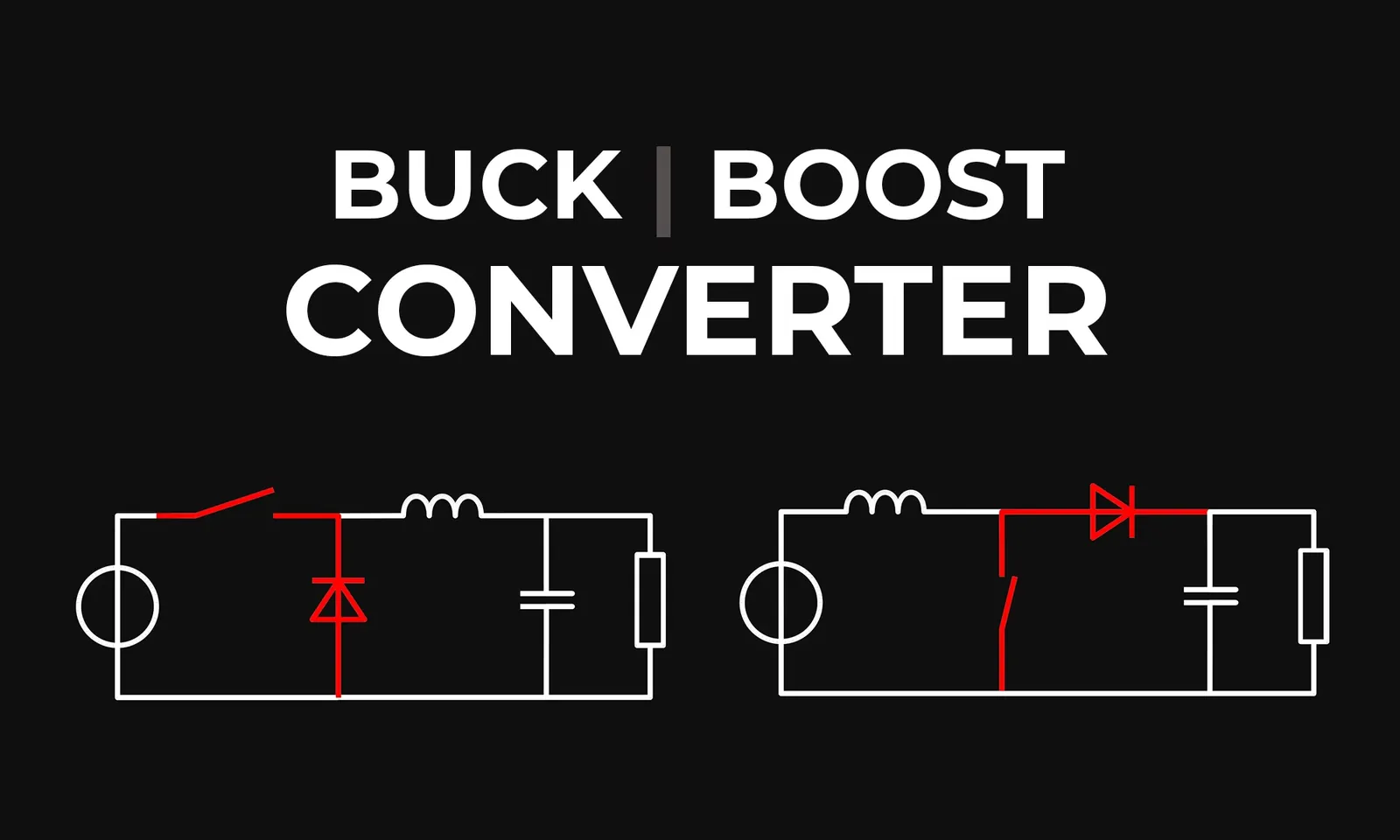
A buck converter, or step-down converter, is a DC-to-DC power converter that takes a higher input voltage and reduces it to a lower output voltage. It’s highly efficient compared to linear regulators because it doesn’t dissipate excess energy as heat. Instead, it uses a high-frequency switch to chop the input voltage into pulses, which are then smoothed out by a filter consisting of an inductor and a capacitor.
How it achieves step-down
The core mechanism involves a pulse-width modulation (PWM) controller. By varying the duty cycle of the switch—the ratio of “on” time to “off” time—the converter determines the average output voltage. When the switch is closed, current flows from the source into the inductor, building a magnetic field. When the switch opens, the energy stored in the inductor is released into the load through a diode.
| Component | Function in Buck Converter |
|---|---|
| MOSFET Switch | Rapidly connects/disconnects the input power |
| Inductor | Stores energy and prevents current spikes |
| Output Capacitor | Smoothes voltage ripple for stable output |
| Schottky Diode | Provides a path for current when switch is off |
Exploring the Buck-Boost Converter
When your power supply voltage is unstable or variable—such as when drawing power from a battery that drains over time—a buck-boost converter is the ideal solution. This topology can handle input voltages that fluctuate above and below the target output. It essentially combines the properties of a buck converter and a boost converter into a single unit.
Working principle of buck-boost
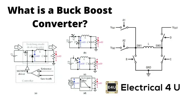
In this configuration, the converter can either step down (buck) or step up (boost) the input voltage based on the duty cycle of the controller. Because the output is typically inverted in polarity compared to the input, these are sometimes called inverting converters. Advanced four-switch controllers are often used today to provide non-inverting buck-boost functionality, which is essential for modern high-end portable devices.
Why use switching regulators?
Switching regulators are preferred over linear regulators in almost every modern application because of their superior power conversion efficiency. Linear regulators work by acting as a variable resistor, burning off the difference between input and output voltage as heat. In contrast, switching regulators cycle on and off, which inherently minimizes power loss.
Benefits of switching technology
- Compact size due to smaller heat sinks.
- Lower energy consumption for battery-powered gear.
- Capability to handle much higher current loads.
- Excellent performance across a wide input range.
How do inductors store energy?
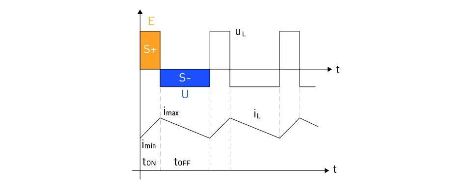
The inductor is the heart of both converters. It operates based on the principle of electromagnetic induction. As current flows through the inductor, it creates a magnetic field. When the switch cuts off the input power, the magnetic field collapses, inducing a current that continues to flow into the circuit. This keeps the load powered during the “off” phase of the switching cycle.
Warning: Never attempt to operate a switching regulator without a properly sized output capacitor, as the resulting voltage ripple can permanently damage sensitive microcontrollers or logic chips.
Choosing the right converter
Selecting the appropriate hardware depends entirely on your input source and your target load requirements. If you’re powering a 5V LED array from a 12V battery, a standard buck converter is sufficient. If you’re using a solar panel that may output anywhere from 3V to 15V to charge a 9V battery, a buck-boost converter is mandatory.
| Scenario | Recommended Converter |
|---|---|
| High voltage to low voltage | Buck Converter |
| Low voltage to high voltage | Boost Converter |
| Variable voltage to fixed voltage | Buck-Boost Converter |
Key components in converter design
To build or select a high-quality converter, you must pay attention to the specific parts used in the circuit. The selection of the switching MOSFET is critical; it must have a low “on” resistance to keep efficiency high and heat low. Similarly, the inductor must be rated for the maximum expected current to prevent magnetic saturation, which would cause the converter to lose its regulation capability.
Essential parts list
- Switching Controller ICs: Such as those manufactured by Texas Instruments or Analog Devices.
- Low ESR Capacitors: Essential for minimizing output ripple voltage.
- Fast Recovery Diodes: Required to handle high-frequency switching without excessive loss.
- Power Inductors: Must be shielded to prevent electromagnetic interference (EMI) with other circuits.
Troubleshooting common power issues
If your converter isn’t performing as expected, start by checking the input voltage stability. Use an oscilloscope to view the switching waveform; a noisy or irregular waveform often indicates a failing capacitor or a poorly laid out circuit board. Ensure that the ground planes are solid, as switching regulators are highly sensitive to ground loops and improper return paths.
Pro Tip: Always place the input decoupling capacitor as close as possible to the power pin of the switching IC to reduce high-frequency noise and improve overall stability.
Efficiency and heat management
Efficiency is the primary metric for any power converter. Most modern designs achieve efficiencies between 85% and 95% according to the International Electrotechnical Commission standards for power electronic components. If your converter is running excessively hot, it’s likely due to switching losses in the MOSFET or excessive resistance in the inductor windings. Always verify that your components are rated for the thermal environment of your enclosure.
Related guides
Frequently Asked Questions
Can a buck converter increase voltage?
No, a buck converter is strictly designed to step down a higher input voltage to a lower output voltage. If you need to increase the voltage, you must use a boost converter or a buck-boost converter. Attempting to force a buck converter to raise voltage will fail and could potentially damage the control circuitry or the connected load due to improper feedback loops.
What is the purpose of the diode?
In a standard buck converter, the diode—often a Schottky type—provides a “freewheeling” path for the inductor current when the main switch is turned off. This prevents the current from being interrupted abruptly, which would cause a massive, damaging voltage spike. In synchronous buck converters, this diode is often replaced by a second MOSFET to increase efficiency by reducing conduction losses.
Why does my converter get hot?
Heat is usually a result of power dissipation caused by internal resistance in the components or switching losses. If the MOSFET or inductor is undersized for the current, it will heat up rapidly. Additionally, poor PCB layout, such as long, thin traces carrying high current, can create significant heat. Ensure that your traces are wide enough to handle the current and that cooling is adequate.
Are buck and buck-boost the same?
They’re fundamentally different. A buck converter only reduces voltage, whereas a buck-boost converter can both increase and decrease voltage to maintain a stable output. The buck-boost is more versatile but often more complex to design and slightly less efficient than a dedicated buck converter. You should only choose a buck-boost if your specific application requires handling both high and low input voltages.
How do I calculate the duty cycle?
The duty cycle is calculated by dividing the output voltage by the input voltage, assuming an ideal converter. For a buck converter, the formula is D = Vout / Vin. In real-world applications, you must also account for efficiency losses, so the actual duty cycle will be slightly higher to compensate for the voltage drops across the switch, diode, and inductor.
Conclusion
Power electronics design requires careful attention to detail, especially when selecting components that handle high energy densities. Whether you’re building a simple hobbyist circuit or a complex industrial power supply, understanding the fundamental differences between buck and buck-boost topologies is the most critical step. Start by prototyping your design on a breadboard using a modular buck-boost board to verify your voltage requirements before committing to a final, permanent PCB layout.
