
If you searched for an ohms law calculator, you need to find voltage, current, resistance, or power in a circuit quickly. Ohm’s Law defines the relationship between these electrical values using simple math. You don’t need expensive software to solve basic circuit problems; knowing the core formulas allows you to calculate any missing variable as long as you have two known values.
Key Takeaways

- Voltage equals current multiplied by resistance (V = I × R).
- Always convert milliamps to amps before calculating to avoid decimal errors.
- Power dissipation requires multiplying voltage by current (P = V × I).
- A standard digital multimeter from Fluke or Klein Tools measures the two values needed for calculation.
- Exceeding a resistor’s wattage rating causes overheating and potential fire hazards.
- Series circuits add resistance together, while parallel circuits reduce total resistance.
What Is Ohms Law?
Ohm’s Law is a foundational principle in electronics formulated by Georg Simon Ohm in 1827. It states that the electrical current flowing through a conductor is directly proportional to the voltage applied across it and inversely proportional to its resistance. This means if you increase the voltage, the current increases, provided the resistance stays constant. If you increase the resistance, the current drops.
The law applies strictly to ohmic materials, which are components that maintain a constant resistance regardless of the voltage applied. Standard carbon film resistors and copper wires are excellent examples of ohmic materials. Components like diodes or transistors are non-ohmic because their resistance changes depending on the voltage or temperature, meaning this specific mathematical relationship doesn’t apply to them linearly.
The Core Formulas Explained
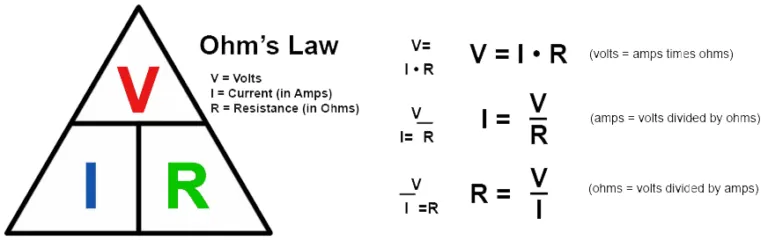
To solve any basic direct current circuit problem, you only need to memorize three primary equations. These equations allow you to isolate any single variable when the other two are known.
- Voltage (V): V = I × R
- Current (I): I = V / R
- Resistance (R): R = V / I
In these formulas, V represents voltage measured in volts, I represents current measured in amperes, and R represents resistance measured in ohms. When working with real-world electronics, you’ll frequently encounter smaller units. Always convert millivolts to volts or kilo-ohms to ohms before plugging numbers into your calculations to ensure accuracy.
How Do You Calculate Power?
Power is the rate at which electrical energy is transferred by a circuit, measured in watts. While Ohm’s Law covers voltage, current, and resistance, adding power expands your ability to design safe circuits. You can derive power formulas by combining the basic Ohm’s Law equations.
- P = V × I
- P = I² × R
- P = V² / R
Knowing the power dissipated by a component is critical for selecting the right parts. For example, if a resistor dissipates 0.5 watts, you must use a resistor rated for at least 1 watt to provide a safety margin. Using a standard quarter-watt resistor in this scenario would cause it to burn out immediately.
Using an Ohms Law Calculator
When you need fast results without doing mental math, an online tool handles the algebra instantly. You simply input two known values—such as a 12-volt battery and a 4-ohm speaker—and the system outputs the remaining variables, including the 3 amps of current flowing through the circuit.
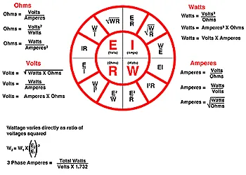
These tools are particularly useful when dealing with complex decimals or large numbers that are prone to manual entry errors. Instead of manually dividing 120 volts by 330 ohms, you enter the figures and get exactly 0.363 amps. Many printed reference cards also feature the Ohm’s Law wheel, a visual diagram showing all twelve possible formula variations arranged in a circle for quick reference.
Pro Tip: Always double-check your unit prefixes before entering data. Entering 500 milliamps as 500 instead of 0.5 will result in a calculation that’s off by a factor of one thousand, potentially leading to dangerous component selection.
Practical Examples for Common Circuits
Applying these formulas to real hardware makes the math easier to understand. Below are typical scenarios you might encounter when working with standard electronic components.
| Scenario | Known Values | Formula Used | Calculated Result |
|---|---|---|---|
| LED Current Limiting | 5V source, 2V LED drop, 330Ω resistor | I = (5 – 2) / 330 | 9.09 mA |
| Car Audio Speaker | 14.4V alternator output, 4Ω speaker | P = (14.4²) / 4 | 51.84 Watts |
| Heater Element | 120V wall outlet, 10A draw | R = 120 / 10 | 12 Ohms |
In the LED example, you must subtract the forward voltage of the LED from the source voltage before dividing by the resistance. Failing to account for the voltage drop across the diode will result in an incorrect current calculation, which could destroy the LED.
Which Multimeters Measure These Values?
To get the inputs required for your calculations, you need reliable test equipment. A good digital multimeter measures voltage, current, and resistance directly from your physical circuit.
- Fluke 115: A highly durable meter favored by industrial electricians for accurate true-RMS measurements.
- Klein Tools MM400: An affordable, auto-ranging option suitable for hobbyists and home repair tasks.
- Uni-T UT61E+: A popular choice for electronics enthusiasts requiring high resolution and PC connectivity.
Warning: Never measure current by placing the multimeter probes in parallel with a power source. To measure current, the meter must be placed in series with the circuit so the electricity flows through the meter itself. Placing it in parallel creates a dead short, which will blow the internal fuse of your multimeter or cause severe injury.
Understanding Series and Parallel Resistance
Calculations become slightly more involved when multiple resistors are present. The configuration of the components dictates how you determine the total resistance before applying the main formula.
Series Circuits
In a series circuit, components are connected end-to-end. The total resistance is simply the sum of all individual resistors. If you have a 100-ohm and a 220-ohm resistor in series, the total resistance is 320 ohms. The same current flows through every component in this arrangement.
Parallel Circuits
In a parallel circuit, components share the same two nodes. The total resistance decreases and is calculated using the reciprocal formula: 1/R_total = 1/R1 + 1/R2. Two identical 100-ohm resistors in parallel yield a total resistance of 50 ohms. The voltage remains constant across all parallel branches.
| Circuit Type | Total Resistance Formula | Current Behavior | Voltage Behavior |
|---|---|---|---|
| Series | R1 + R2 + R3 | Same through all components | Divides across components |
| Parallel | 1 / (1/R1 + 1/R2) | Divides among branches | Same across all branches |
Does Temperature Change Resistance?
Yes, environmental factors significantly impact electrical properties. For most metallic conductors like copper wire, resistance increases as temperature rises. This relationship is defined by the temperature coefficient of the material.
This is why incandescent light bulbs draw a massive surge of current the instant they’re turned on. The tungsten filament has very low resistance when cold, but as it heats up to thousands of degrees, its resistance climbs drastically, stabilizing the current flow.
When performing precise calculations for sensitive analog circuits, engineers must account for ambient operating temperatures to prevent signal drift. You can review detailed specifications regarding electrical safety and component ratings through UL standards certification documentation, which outlines testing requirements for thermal limits.
Troubleshooting Common Calculation Errors
Even experienced technicians make mistakes when rushing through circuit analysis. Identifying these pitfalls early saves time and prevents damaged components.
- Unit mismatch: Mixing kilohms with milliamps without converting everything to base units (volts, amps, ohms) first.
- Ignoring tolerance: Assuming a 100-ohm resistor is exactly 100 ohms, when a 5% gold-band resistor could actually be anywhere between 95 and 105 ohms.
- Overlooking power ratings: Calculating the correct resistance value but installing a physically small resistor that can’t handle the resulting heat dissipation.
- Measuring under load: Attempting to measure a component’s resistance while the circuit is still powered on, which gives false readings and risks damaging the meter.
Always verify your calculated results against the physical limitations of the components you intend to use. Math might say a circuit works perfectly, but physics dictates whether the parts survive.
Related guides
Frequently Asked Questions
What are the three forms of Ohm’s Law?
The three primary forms isolate each variable: Voltage equals current times resistance (V = I × R), current equals voltage divided by resistance (I = V / R), and resistance equals voltage divided by current (R = V / I). These allow you to find any missing value if you know the other two.
Can I use Ohm’s Law for alternating current?
You can use it for purely resistive AC circuits, like a basic space heater. However, if the circuit contains capacitors or inductors, you must replace standard resistance with impedance (Z). The modified formula becomes V = I × Z to account for phase shifts.
Why is my calculated current different from measured current?
Real-world components have manufacturing tolerances. A resistor marked as 1,000 ohms might actually measure 980 ohms. Additionally, batteries experience internal resistance and voltage drop under heavy loads, meaning the actual voltage delivered to your circuit is lower than the battery’s nominal rating.
How many watts is 12 volts at 2 amps?
Power is calculated by multiplying voltage by current. Therefore, 12 volts multiplied by 2 amps equals exactly 24 watts. This tells you the total amount of electrical energy being consumed or dissipated by the circuit at that specific operating point.
What happens if resistance drops to zero?
If resistance reaches zero, the current theoretically becomes infinite, creating a short circuit. In reality, the power supply will either hit its maximum current limit, trigger a protective breaker, or overheat and fail. Short circuits are extremely dangerous and cause fires.
Conclusion
Now that you understand the relationships between voltage, current, resistance, and power, grab a digital multimeter and measure a simple battery-powered circuit in your home. Calculate the expected values using the formulas above, then compare your math against the physical measurements to build practical confidence.
