
A complete guide to linkage mechanisms covers how rigid bars connected by joints turn one movement into another. These systems appear in car suspensions, door hinges, folding chairs and robotic arms.
What linkage mechanisms are
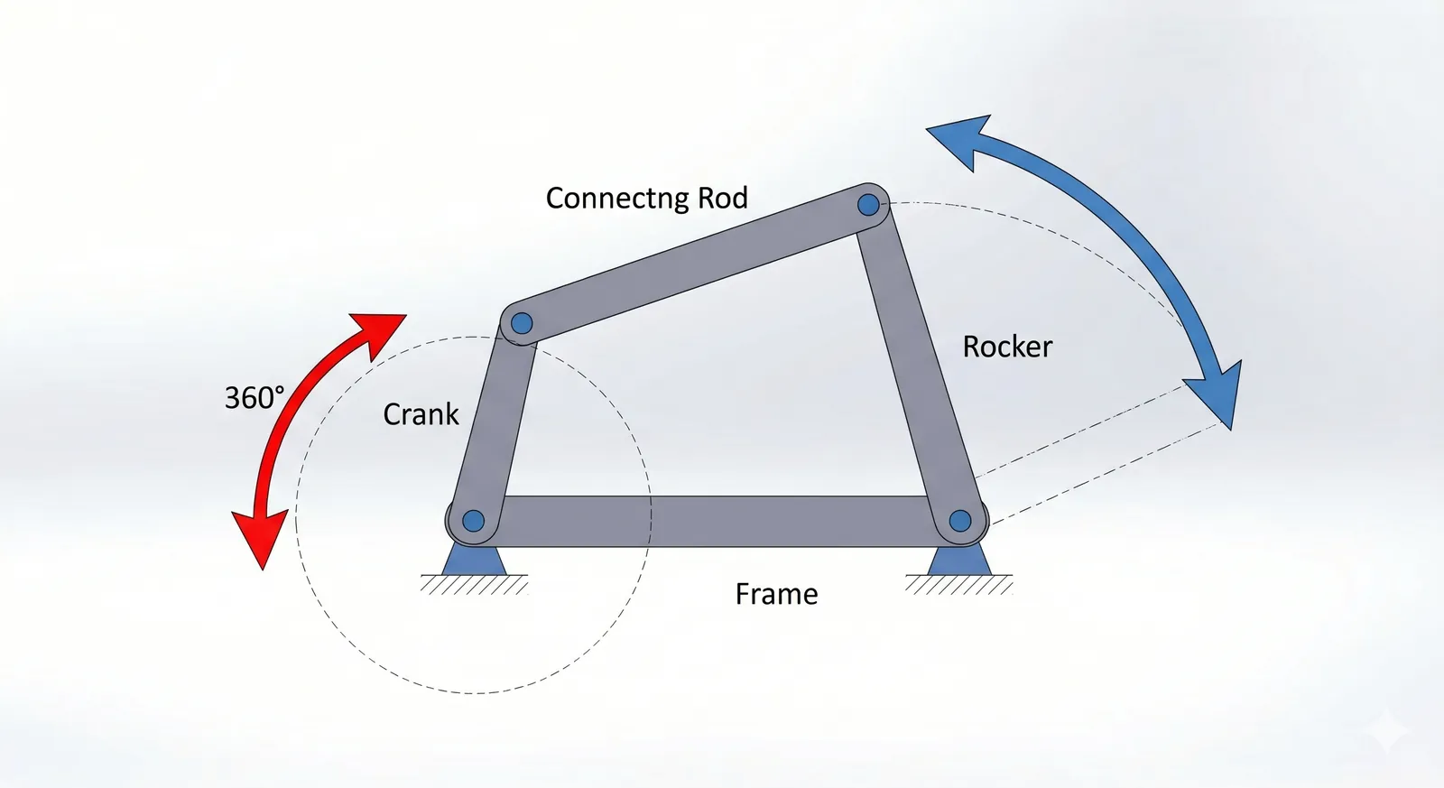
A linkage mechanism is a set of rigid bars, called links, joined at pivot points so they guide motion from one part of a machine to another. Engineers use them to change the direction, speed or distance of a movement — for example, turning a rotating crank into a back-and-forth push in an engine, or keeping a tool level as it moves.
The most common versions use four bars, though six-bar and eight-bar designs exist for more complex paths. One common misconception is that adding more links always adds precision; in practice, extra joints add looseness unless every pivot is tight.
A four-bar linkage follows Grashof’s rule: if the shortest link plus the longest link is less than or equal to the sum of the other two links, at least one link can rotate fully. You can verify link proportions and Grashof’s condition using the mechanism design references published by MIT OpenCourseWare.
How to build a basic linkage
- Decide the motion you need — rotating, rocking or sliding — and pick the fixed pivots where the frame will hold the linkage.
- Measure the distance between those fixed pivots; this is your frame link and every other length is sized against it.
- Cut four rigid bars to the lengths your motion requires, with holes at each end for the pivots.
- Bolt the bars together at the moving joints, leaving enough clearance that they swing without binding.
- Anchor the frame link to its fixed pivots and test the full range of motion by hand.
- Check that no bar crosses another or hits the frame at any point in the travel.
- Tighten every pivot and add a stop or damper if the end of travel needs cushioning.
The single judgement call is the pivot clearance: too tight and the mechanism binds; too loose and it wobbles, losing the exact motion you wanted. If a joint must carry heavy loads or repeat thousands of cycles, use bearings or bushings and have a machinist check the fit.
A complete guide to linkage mechanisms and their uses
| Situation | What to use | How long it takes to set up | What to watch for | | Four-bar, one input rotates fully | Crank-rocker | About an hour for a simple model | The rocker must not reach a dead-center position | | Four-bar, both inputs rock | Double-rocker | About an hour | Neither link completes a full turn | | Straight-line output needed | Watt or Scott-Russell linkage | Several hours to fit | Small errors in link length bend the line | | Parallel motion for a platform | Parallel linkage | About an hour | All four pivots must stay in one plane | | Complex path for a robot arm | Six-bar or eight-bar | A day or more | Every extra joint adds play and wear |
Details that separate good results from bad ones
Good linkage design starts with accurate pivot placement. A hole drilled off by a millimetre changes the whole path, so experienced builders mark both sides of a part before drilling and ream the holes to a sliding fit for the pins. They also work in one plane: if the pivots aren’t coplanar, the links twist under load and wear out fast.
Partway through assembly, they cycle the linkage slowly by hand and watch for binding or a joint that reaches its limit before the others. What they leave alone is just as important — they don’t grease pivots that run dry by design, and they don’t add links just to look more complex. Each extra joint is a place for slack to collect, so the simplest linkage that delivers the motion is usually the best one.
Problems and fixes

| What you notice | What it usually means | What to do first | | Clicking or looseness at a joint | Worn pin or oversized hole | Replace the pin or fit a bushing | | Mechanism sticks at one point | Links bind or hit a dead center | Check clearance and adjust link lengths | | Output path wobbles | Pivots aren’t in one plane | Realign the mounting brackets | | Motion stops short | A bar interferes with the frame | Add clearance or shorten the stroke |
Rules and standards that apply
Machine guarding rules come from the Occupational Safety and Health Administration, which requires moving parts that could injure someone to be guarded. Linkages used in vehicles or aircraft fall under the rules of the Department of Transportation or the Federal Aviation Administration, depending on the craft.
If you’re designing a product for sale, the relevant voluntary consensus standards are published by ASTM International and ASME. Any step that involves welding, load-bearing joints or public-facing machinery needs a qualified engineer — don’t guess at strength or fatigue life.
Keeping a linkage working
Check pivot tightness every few months on a heavily used mechanism, and sooner if you hear clicking or feel play. Keep the pivots clean and lubricated according to the manufacturer’s guidance, unless the joint uses sealed bearings that need no grease.
Record the link lengths and pivot positions so a replacement part can be machined to match. The mechanism holds up until wear at the joints creates visible slack — that’s the sign it’s due for attention, not a fixed calendar date.
When measuring those links, record the center-to-center distance between holes rather than overall length. A new part cut to overall length will bind if the hole spacing differs by even a fraction of a millimeter.
People often tighten a loose pivot past its original torque to stop a rattle. That crushes the bushing inside the joint and accelerates wear far beyond what the slack would have caused. Snug the fastener only until the play disappears.
When a linkage is the wrong choice
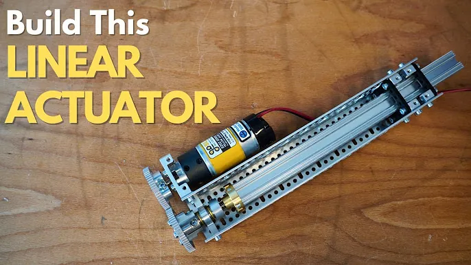
A linkage is the wrong choice when you need very high precision over a long travel — a leadscrew or linear guide holds position better. It’s also the wrong choice when the force is very large and constant, because every pivot concentrates load and wears; a hydraulic cylinder handles that more directly.
And if the motion must be fully programmable, a servo-driven mechanism beats a fixed set of bars. In each of those cases, choose the alternative that matches the load, precision and control you need.
Related guides
Frequently asked questions
What is a linkage mechanism used for?
It changes one motion into another — rotating into back-and-forth, or one path into another — inside machines, tools and vehicles.
Can one linkage produce a straight line?
Yes, but only approximately over a limited range; a Watt linkage or Scott-Russell linkage comes close within its designed travel.
How many bars does a simple linkage have?
Four bars form the simplest closed linkage, sized against the fixed distance between its two frame pivots.
Is it safe to guard moving linkages?
Yes — OSHA requires guards on moving parts that could injure someone, and the guard must not create a new pinch point.
What happens if a pivot is loose?
The output motion becomes inaccurate and the joint wears faster; replace the pin or fit a bushing.
How long does a linkage last?
It lasts until joint play becomes visible; check tightness every few months on heavy use, with no fixed replacement interval.
What should I use instead of a linkage?
Use a leadscrew for precise straight travel, a hydraulic cylinder for high constant force, or a servo system for programmable motion.
Conclusion
Linkage mechanisms turn simple inputs into useful outputs, but only when the pivots are tight, the links are the right length, and the design matches the job. Check your own travel, load and precision needs before choosing the number of bars, and go to a qualified engineer whenever the joint carries a load that could hurt someone if it failed.
