
An electrical contactor is a heavy-duty relay designed to switch power circuits on and off. If you searched for a complete guide to electrical contactors, you’re probably trying to wire one, size one, or figure out why one keeps failing. Contactors are the workhorses behind electric motors, HVAC compressors, lighting banks, and industrial machinery. They use a small control signal—often 24 V, 120 V, or 230 V—to close heavy-duty main contacts that carry much larger loads, sometimes hundreds of amps at 480 V or more. Because they’re built for frequent operation, they outlast manual switches and general-purpose relays in demanding applications.
Key Takeaways

- Match the contactor to the load: use horsepower, full-load amps, and voltage ratings, not just the wire size.
- Size the coil voltage to your control circuit—common choices are 24 V, 120 V, 230 V, and 480 V.
- Add overload protection separately; a contactor switches power but doesn’t by itself protect a motor from overload.
- Use auxiliary contacts for control-circuit interlocking and status indication.
- Replace a contactor when main contacts show pitting, welding, or excessive heating.
What Is an Electrical Contactor
An electrical contactor is an electrically controlled switch used for switching a power circuit. Unlike a simple wall switch, it’s operated remotely by energizing an electromagnetic coil. When the coil receives voltage, it creates a magnetic field that pulls in a set of main contacts, completing the circuit to the load. When the coil is de-energized, springs snap the contacts open, breaking the circuit.
Contactors differ from relays primarily in duty and construction. Relays typically handle low-power control signals, while contactors are built for motor loads, capacitor banks, and lighting circuits that draw high inrush current. Contactors also feature arc suppression, replaceable contacts in many industrial models, and auxiliary contact blocks for signaling and interlocking.
Main Parts of a Contactor
Every contactor has three functional sections: the coil system, the main power contacts, and the auxiliary contacts.
- Coil system: The electromagnet that opens and closes the main contacts. It’s rated for a specific coil voltage, such as 120 V AC or 24 V DC.
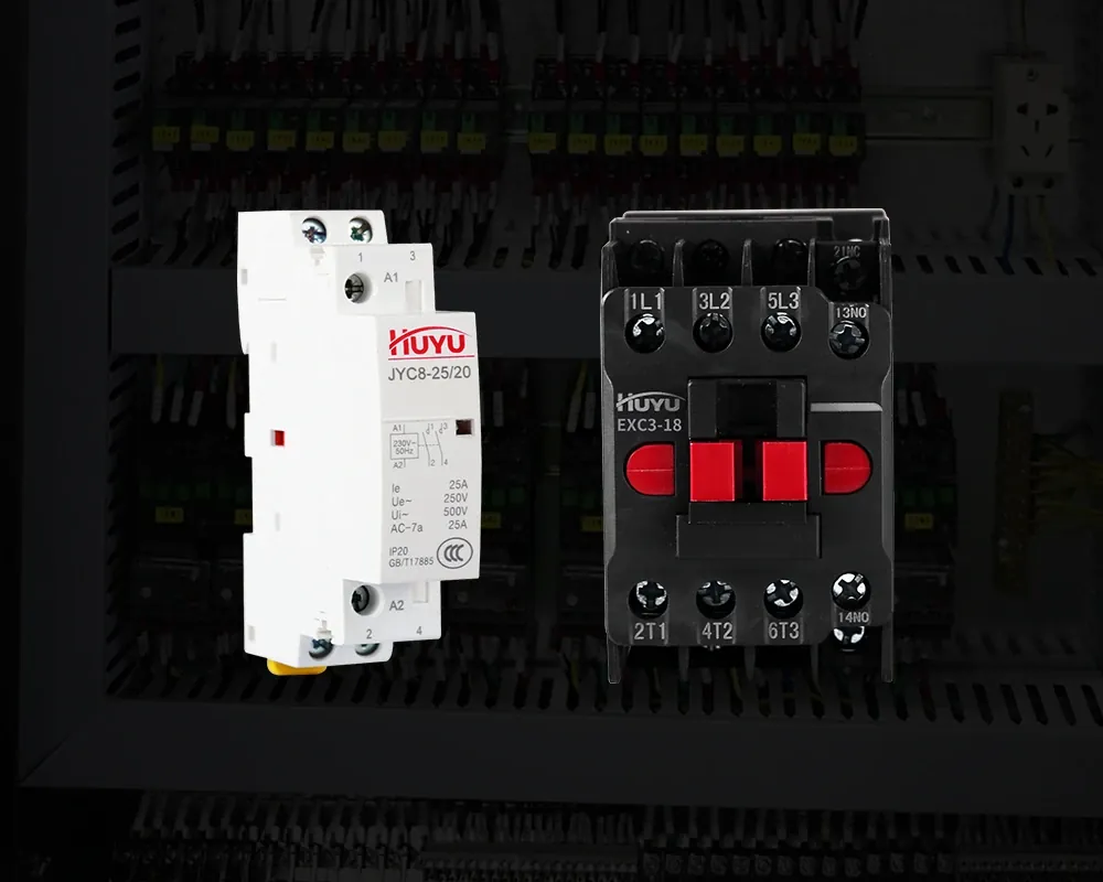
- Main contacts: Heavy-duty silver-alloy contacts that carry the load current. Three-pole contactors switch all three phases of a motor; single-pole and two-pole versions exist for smaller loads.
- Auxiliary contacts: Smaller contacts used in control circuits. They can indicate that the contactor is closed, or they can interlock with other devices so two motors can’t run at the same time.
- Frame and arc chutes: The housing that contains the contacts and extinguishes the arc formed when contacts separate under load.
Contactor Types and Ratings
Contactors are classified by pole count, load type, and enclosure. The most common categories are:
- Definite-purpose contactors: Used in HVAC, refrigeration, and residential compressors. Rated for specific applications such as air conditioning or resistive heating.
- Industrial contactors: Modular, heavy-duty units with replaceable contacts and a wide range of coil voltages. Common in motor control centers and factory automation.
- Lighting contactors: Designed for the high inrush of fluorescent or LED ballasts and tungsten lamp loads.
- Capacitor switching contactors: Equipped with damping resistors or special contact materials to handle the inrush of power-factor correction capacitors.
Contactor ratings appear on the nameplate and include:
- Rated operational current (Ie) at specific voltages.
- Horsepower ratings for single-phase and three-phase motors.
- Short-circuit current rating, which tells you how much fault current the device can withstand with proper upstream protection.
- Mechanical and electrical life, usually expressed in operations.
A Complete Guide to Sizing Electrical Contactors

Sizing a contactor isn’t the same as sizing a circuit breaker. You must match the device to the load it will switch, considering motor horsepower, full-load current, and duty cycle.
- Identify the load voltage and full-load amps from the motor nameplate.
- Select a contactor whose rated operational current equals or exceeds the load current at that voltage.
- Check the horsepower rating against your motor size; don’t exceed it.
- Choose a coil voltage available from your control circuit.
- Verify the short-circuit rating works with your upstream breaker or fuses.
The table below shows typical selection criteria for common motor voltages.
| Load Voltage | Typical Coil Voltages | Common HP Range | Typical Contactor Frame |
|---|---|---|---|
| 120 V single-phase | 24 V, 120 V | 0.5–2 HP | Miniature / definite-purpose |
| 208–230 V single-phase | 24 V, 120 V, 230 V | 1–5 HP | Definite-purpose / industrial |
| 208–230 V three-phase | 120 V, 230 V | 5–50 HP | Industrial |
| 460–480 V three-phase | 120 V, 230 V, 480 V | 10–200+ HP | Industrial |
Always apply a service factor if the motor runs continuously or in high-ambient temperatures. Undersizing causes contact overheating and welded contacts; oversizing wastes panel space and money.
Wiring a Contactor
Wiring a contactor means separating the control circuit from the power circuit. The control circuit energizes the coil; the power circuit carries the load.
Control circuit wiring
- Run one leg of the control voltage to one coil terminal.
- Run the other leg through any control devices—start pushbuttons, stop buttons, overload contacts, or limit switches—to the second coil terminal.
- Use the wire size recommended by the manufacturer, typically 14 AWG or 16 AWG for control circuits.
Power circuit wiring
- Connect incoming line power to the L1, L2, and L3 terminals (or L1 and L2 for single-phase).
- Connect the load—T1, T2, and T3—to the motor or other equipment.
- Torque all power terminals to the manufacturer’s specification; loose connections cause overheating and contact failure.
A three-wire control circuit uses momentary start and stop pushbuttons with a seal-in contact from the contactor’s auxiliary block. A two-wire circuit uses a maintained device such as a thermostat or float switch. Never route control wires in the same conduit as power conductors unless they’re rated for the power voltage.
Contactor vs Relay vs Starter
People often confuse contactors with relays and motor starters. The table below compares them.
| Device | Typical Use | Current Handling | Overload Protection |
|---|---|---|---|
| Relay | Control signals, pilot duty | Low (usually under 10 A) | No |
| Contactor | Motor loads, lighting, heating | High (tens to hundreds of amps) | No, unless paired with an overload relay |
| Motor starter | Motor on/off with overload protection | High | Yes, via overload relay or electronic overload |
A motor starter is essentially a contactor plus an overload relay. The contactor handles the switching; the overload relay senses current and opens the control circuit if the motor draws too much for too long.
Common Brands and Models
Several manufacturers dominate the contactor market. You’ll see these names on nameplates and in distributor catalogs:
- Siemens: SIRIUS industrial contactors and definite-purpose models.
- Schneider Electric: TeSys D and TeSys K contactors.
- Eaton: XT and CE contactor lines.
- ABB: AF and contactor ranges for industrial and IEC applications.
- Honeywell: Definite-purpose contactors common in HVAC and refrigeration.
When replacing a contactor, match the coil voltage, pole count, current rating, and horsepower rating. Physical dimensions and terminal types matter too, especially in existing enclosures.
Troubleshooting Contactors
Contactors fail in predictable ways. The most common symptoms and likely causes are:
- Contactor won’t pull in: Check coil voltage, control circuit fuses, stop buttons, and overload contacts. A burned-out coil reads open on a multimeter.
- Chatters or buzzes: Low voltage to the coil, a dirty shading coil, or mechanical binding. Verify voltage at the coil while energized.
- Main contacts don’t close fully: Worn contact tips, broken springs, or misalignment. Replace the contactor or contact kit.
- Contacts weld together: Overload, short circuit, or cycling beyond the rated electrical life. Replace the unit and investigate the cause before re-energizing.
- Excessive heating: Undersized contactor, loose terminals, or continuous duty beyond rating. Check torque and amp draw.
Warning: Always lock out and tag out power before inspecting or replacing a contactor. Verify absence of voltage with a meter rated for the circuit.
Use a multimeter to check coil resistance and contact continuity. Compare readings to the manufacturer’s data. If contacts are pitted but the coil and mechanics are sound, some industrial contactors allow contact kit replacement rather than full unit replacement.
Pro Tip: Label both the line and load sides before you disconnect anything. A miswired contactor can reverse motor rotation or energize a circuit you believe is off.
Maintenance Schedule
Preventive maintenance extends contactor life and prevents unplanned downtime. The schedule below assumes a typical industrial environment; harsh conditions such as dust, vibration, or high temperature call for more frequent checks.
| Task | Frequency | What to Check |
|---|---|---|
| Visual inspection | Monthly | Contact wear, discoloration, dust, loose wires |
| Terminal torque check | Every 6 months | Power and control terminal tightness |
| Coil voltage check | Every 6 months | Voltage at coil during operation |
| Contact resistance test | Annually | Millivolt drop across main contacts |
| Full functional test | Annually | Pull-in, dropout, and auxiliary contact operation |
Replace contactors that show contact erosion beyond the manufacturer’s limit, or that have experienced a severe short-circuit event even if they appear to work.
Related guides
- 7 Best Drill Bits for Electrical Rough In: Expert Picks in 2026
- Bidet Toilet Seat Electrical Requirements: A Safety Guide in 2026
Frequently Asked Questions
Can I use a contactor without an overload relay?
Yes. A contactor switches power on and off, but it doesn’t sense motor current over time. For motor protection, pair it with an overload relay or use a motor starter that includes one.
How long does a contactor last?
Mechanical life is often millions of operations, while electrical life under load is typically in the range of 100,000 to 500,000 operations depending on load and duty cycle. Actual life depends on switching frequency, load type, and maintenance.
Why does my contactor chatter?
Chattering usually means the coil isn’t receiving enough voltage to hold the contacts closed. Check for voltage drop in the control circuit, loose connections, or a failing power supply. A broken shading coil can also cause AC contactors to chatter.
Can I replace just the contacts?
On many industrial contactors, yes. Manufacturers sell contact kits that include movable and stationary contact assemblies. Definite-purpose and miniature contactors are usually replaced as complete units.
What size contactor do I need for a 5 HP motor?
It depends on voltage and phase. For a 5 HP, 230 V three-phase motor, full-load current is roughly 13 to 14 amps, so a contactor rated at least 18 to 25 amps at that voltage is typical. Always verify against the motor nameplate and the contactor’s horsepower rating.
Conclusion
Selecting the right contactor starts with the load, not the wire. Check the motor nameplate, choose a contactor rated for the voltage and horsepower, match the coil to your control circuit, and add overload protection where motors are involved. If you’re replacing an existing unit, take a photo of the wiring before you disconnect anything, then match the nameplate ratings exactly.
