
The symbols on a multimeter represent the various electrical measurement modes and settings that allow you to diagnose circuits, test components, and ensure your home electronics are functioning safely. By understanding these icons—which are usually standardized across manufacturers like Fluke, Klein Tools, and Extech—you can transition from guessing to precise troubleshooting. Whether you’re checking a battery’s health or verifying that a wall outlet is dead before performing repairs, the dial and button labels provide the essential language for interaction with your device.
Key Takeaways
- Always identify the correct input port before turning the dial to avoid damaging your meter.
- Use the DC setting for batteries and electronics, and the AC setting for standard household wall outlets.
- The continuity mode is your primary tool for finding broken wires or checking if a switch is working.
- Start with the highest range setting if your meter isn’t autoranging to prevent blowing an internal fuse.
- Never attempt to measure current (amps) in parallel with a voltage source, as this creates a dangerous short circuit.
What Do The Symbols Mean?
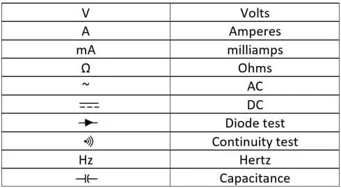
Multimeters use a combination of Greek letters, geometric shapes, and abbreviations to convey information. The most common symbols are derived from the International System of Units. A straight line over a dashed line represents Direct Current (DC), while a wavy line (tilde) represents Alternating Current (AC). Recognizing these is critical because selecting the wrong mode can lead to inaccurate readings or, in extreme cases, internal damage to the meter’s circuitry.
Deciphering Common Measurement Symbols
Understanding the basic dial layout is the first step toward proficiency. Most digital multimeters feature a central dial that rotates to select the function, while specialized buttons might toggle between modes like “Auto” and “Manual” ranging.
| Symbol | Meaning | Typical Application |
|---|---|---|
| V with Tilde (~) | AC Voltage | Wall outlets, household appliances |
| V with Dashed Line | DC Voltage | Car batteries, AA/AAA batteries |
| A with Tilde (~) | AC Current | Heavy machinery, industrial motors |
| A with Dashed Line | DC Current | Solar panels, small DC motors |
| Ω (Omega) | Resistance | Checking resistors, heating elements |
| Continuity Symbol | Circuit Path | Testing for broken wires or fuses |
Understanding The Continuity Test Symbol
The continuity symbol, which looks like a series of radiating sound waves or a small speaker icon, is one of the most useful features for beginners. When you place your probes on two points in a circuit, the meter emits an audible beep if there’s a complete path for electricity to flow. This is the gold standard for identifying a blown fuse or a frayed wire that has lost its physical connection.
Warning: Always ensure the power to the circuit is completely disconnected before testing for continuity. Testing a live circuit in this mode can cause the meter to short out or potentially lead to a dangerous arc flash.
How To Read Voltage Settings
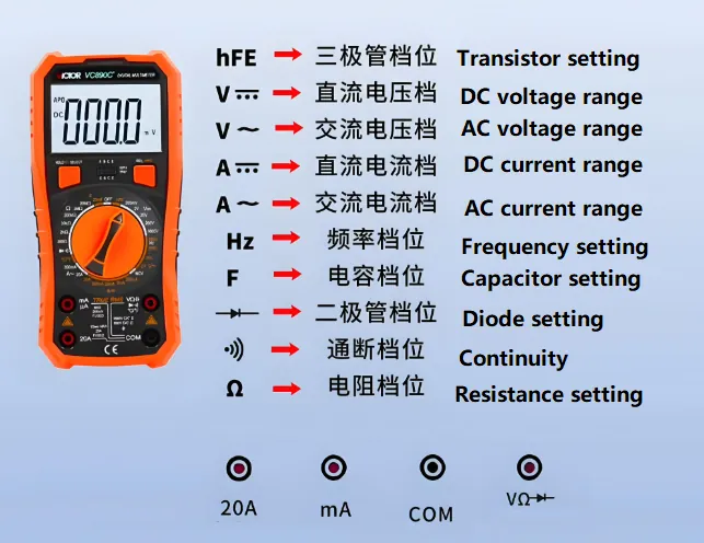
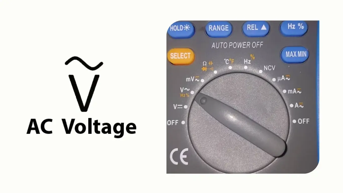
Voltage measurements are divided into two main categories: Alternating Current and Direct Current. AC voltage fluctuates, reversing direction periodically, which is why it’s used for power grids and home electricity. DC voltage flows in a single, constant direction. When using your meter, you must match the setting to the source. If you’re checking a 9V battery, you must select the DC setting; attempting to read it on the AC setting will often result in a zero or erratic reading.
Pro Tip: If your multimeter isn’t an “autoranging” model, always start with the dial set to the highest voltage number available for that mode. If the reading is too small to read accurately, you can then dial it down to a lower range.
Measuring Resistance And The Omega
The Greek letter Omega (Ω) indicates resistance, measured in Ohms. This setting is used to determine how much a component resists the flow of electricity. It’s frequently used for testing the health of heating elements in toasters or stoves. A very low reading (close to zero) suggests a good connection, while an “OL” or “1” reading on the screen usually indicates an “Open Loop,” meaning the resistance is infinite, or the component is broken.
What Does The Diode Symbol Mean?
The diode symbol looks like a small triangle pointing at a vertical line. Diodes are electronic components that act as one-way valves for electricity. This setting allows you to verify if the diode is functioning correctly by measuring the voltage drop across it. It’s a common diagnostic step when fixing circuit boards or power supplies. If the meter displays a small voltage when current flows in one direction and “OL” in the other, the diode is likely healthy.
Interpreting The Current Measurement Ports
Measuring current requires a different physical setup than measuring voltage. While voltage is measured by touching probes to two points, current must be measured by putting the multimeter in series with the circuit. This means the electricity must pass through the meter itself. Because of this, current ports are often fused separately to protect the device. Always check the International Electrotechnical Commission standards regarding category ratings to ensure your meter is safe for the specific environment where you’re working.
Troubleshooting Common Display Errors
- OL or 1: This indicates an “Over Limit” or “Open Loop.” The resistance is too high to measure, or the circuit is broken.
- Zero Reading: If you’re measuring voltage, this usually means there’s no power present or you have the probes on the same potential.
- Flashing Numbers: Some meters flash when the measurement is unstable or the probes are poorly connected.
- Negative Sign: In DC mode, this indicates your probes are reversed; the black probe is on the positive side and the red is on the negative.
Safety Symbols To Know
Beyond the measurement dial, you’ll often see symbols printed near the input jacks. A lightning bolt inside a triangle is the universal warning for high voltage. You might also see a “double square” symbol, which indicates the device is double-insulated, meaning it has extra protection against electric shock. Always inspect your test leads for cracks or exposed metal before every use; a damaged lead is the most common cause of inaccurate readings and potential safety hazards.
Related guides
Frequently Asked Questions
What does the M or K symbol mean?
These are unit prefixes. “K” stands for kilo, meaning the reading is in thousands (e.g., kΩ is thousands of Ohms). “M” stands for mega, meaning the reading is in millions. If your meter shows 10kΩ, that is 10,000 Ohms. Always pay attention to these letters, as ignoring them will lead to massive errors in your calculations when you’re testing components like resistors.
Why does my meter show OL?
“OL” stands for “Open Loop” or “Over Limit.” It means the resistance is higher than what the meter can measure at its current setting, or the circuit is physically broken. If you’re testing a wire for continuity and you see OL, it means the wire is snapped somewhere inside the insulation, preventing the electrical signal from passing from one end to the other.
Can I measure AC with DC settings?
No, you cannot. If you attempt to measure AC voltage using a DC setting, the meter will likely display a very low, fluctuating, or nonsensical number. This is because the meter is trying to average the alternating wave as if it were a steady, unidirectional flow. It isn’t dangerous to the meter, but it won’t provide you with the correct voltage value you need.
What is the hFE setting?
The hFE setting is used to test the gain of transistors. It’s an older feature found on many hobbyist meters. Unless you’re building or repairing circuits with individual transistors, you’ll rarely need to use this setting. It involves inserting the three pins of a transistor into the small specialized slots located on the face of the multimeter to determine if it’s still amplifying correctly.
Should I use Auto or Manual?
If your meter has an “Auto” mode, use it. It automatically selects the best range for the signal it detects, preventing errors where you might pick a range that’s too low to display the result. Manual ranging is only necessary for advanced troubleshooting, such as when you’re looking for specific, tiny fluctuations in a signal that the autoranging feature might accidentally filter out or skip over.
Conclusion
Mastering these symbols transforms your multimeter from a confusing box of wires into a reliable diagnostic partner. Start by practicing on simple items like batteries or spare fuses to build your confidence.
Always verify your lead placement before turning on the power, and when in doubt, default to the highest range setting to protect your equipment. Your next step is to grab your manual, locate your specific meter model, and identify these symbols on your own device to see how they align with the standard labels discussed here.
