
A positive temperature coefficient is a material property where electrical resistance increases as the temperature rises. This behavior happens in most pure metals, such as copper, tungsten, and nickel. When you heat these materials, the atoms vibrate more vigorously, which causes more collisions with moving electrons and slows them down. This increased scattering creates electrical resistance that grows predictably as the heat increases.
How a positive temperature coefficient works
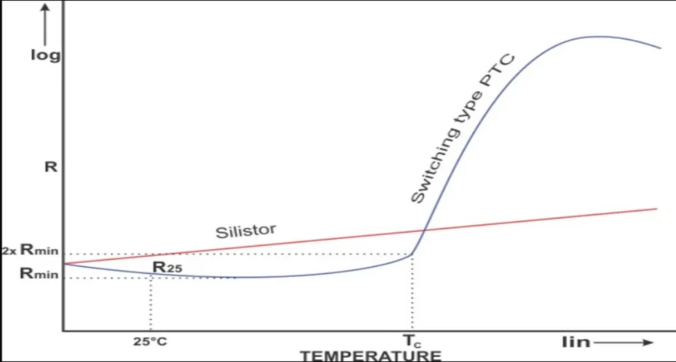
The way a material responds to heat is a fundamental property that dictates how it functions in a circuit. Engineers use this relationship to design sensors, heaters, and safety switches that respond to ambient conditions. If the temperature of a metal conductor goes up, the resistance moves up with it; if the temperature drops, the resistance decreases accordingly.
This relationship is linear for many metals within a specific operating range. You can calculate the exact resistance change using the temperature coefficient of resistance constant, which is unique to each material. Manufacturers provide this value on data sheets to help you predict how a component will behave when it gets hot during normal use.
Key Facts About Resistance Behavior
- Copper exhibits a positive temperature coefficient of approximately 0.00393 per degree Celsius at 20°C.
- Most pure metals increase in resistance as they get hotter, which limits the current flow through them.
- Light bulbs use tungsten filaments because their resistance rises as they heat up, which helps protect the circuit.
- Engineers use this property to create resistance temperature detectors, or RTDs, for precise temperature measurement.
- The International Electrotechnical Commission sets global standards for how these components are tested and classified.
- You can identify this behavior by measuring the resistance of a cold component and comparing it to its resistance when hot.
Why Materials Change Resistance
The movement of electrons through a metal lattice is the primary reason for this change in resistance. In a cold metal, the atoms are relatively still, allowing electrons to flow with fewer interruptions. As thermal energy enters the system, the atoms begin to oscillate in their positions, creating a more chaotic environment for the passing electrons.
These increased vibrations act like a crowded hallway, making it harder for electrons to pass through without bumping into the metal atoms. Each collision absorbs some energy from the electron, which manifests as electrical resistance. This is why a simple copper wire will have slightly higher resistance after it has been carrying a high current for several minutes.
This effect isn’t infinite, as every material has a physical limit where it may change state or melt. If you’re designing a circuit, you must check the component’s maximum operating temperature to ensure the resistance doesn’t exceed the needs of your system. You can find these limits in the technical specifications provided by the component manufacturer for your specific part.
When Resistance Behavior Differs
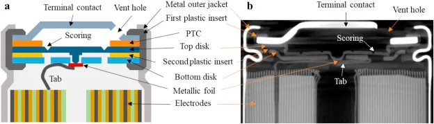
Not all materials follow this linear rule, as some exhibit a negative temperature coefficient where resistance falls as heat increases. The following table highlights common scenarios where the response to temperature change is different.
| Situation | What changes | What to do instead |
|---|---|---|
| Semiconductor materials | Resistance drops when hot | Use specialized cooling systems |
| Carbon components | Resistance often decreases | Allow for thermal compensation |
| Electrolytic solutions | Ion mobility increases | Monitor for chemical degradation |
| Superconductors | Resistance hits zero | Maintain extreme cryogenic cooling |
| Ceramic thermistors | Resistance changes sharply | Use a lookup table |
If you’re working with precision sensors, assume the standard linear model will fail you. A common mistake is ignoring the self-heating effect caused by current flow, which can trigger a thermal runaway loop in semiconductors due to their negative temperature coefficient. In these cases, you must integrate a feedback loop that adjusts the voltage dynamically to maintain stability.
How to Measure Resistance Changes
To determine how a component reacts to heat, you need a precise multimeter and a controlled heating source. Follow these steps to observe the effect safely without damaging your equipment.
- Measure the baseline resistance of your component while it’s at room temperature using a digital multimeter.
- Record this value in ohms, ensuring your probes make solid contact with the terminals to avoid false readings.
- Apply a controlled heat source, such as a heat gun or a temperature-controlled oven, to the component.
- Wait for the component to reach a stable, higher temperature, then measure the resistance again quickly.
- Subtract the baseline value from the new reading to find the total change in resistance for that temperature jump.
- Compare your result against the material’s published coefficient to see if it matches the expected behavior for that metal.
Common Mistakes That Ruin Results

Measuring resistance while the circuit remains energized will blow your multimeter’s internal fuse or destroy the sensitive sensing circuitry entirely. Always verify zero voltage before touching a probe to a terminal.
Holding both metal probes with your bare fingers introduces your body’s own resistance into the circuit. This creates a parallel path that artificially lowers the reading, especially when measuring high-impedance components above 100k ohms. Use alligator clips instead to ensure a clean, isolated connection.
Components often drift as they settle from the heat of your soldering iron or a warm hand. Wait at least sixty seconds after initial contact for the reading to stabilize. If the numbers continue to climb or fall steadily, the component hasn’t reached thermal equilibrium.
Finally, ignore the ambient temperature at your own risk. Resistance values shift significantly in cold environments versus hot ones. If your workspace is below 60°F or above 85°F, calibrate your expectations against a known reference resistor first.
Frequently asked questions
Can a wire change resistance if it gets hot?
Yes, a copper or aluminum wire will increase in resistance as it gets hotter during operation. This happens because the metal atoms vibrate more, which creates more obstacles for the flowing electrons. If a wire runs too hot, the increased resistance causes even more heat, which can eventually damage the insulation or the connection points.
Why do some components lose resistance when hot?
Components like thermistors or semiconductors have a negative temperature coefficient, meaning their internal structure allows for better electron flow as heat increases. This is the opposite of pure metals. Engineers use these specific materials when they need a device to become more conductive as the environment warms up, such as in temperature-sensitive control circuits.
How do I know if my component has a positive temperature coefficient?
You can check the technical data sheet provided by the manufacturer, which lists the temperature coefficient of resistance for the specific material used. If the value is positive, the resistance will rise as the temperature climbs. You can also verify this by heating the component slightly and observing a rise in the resistance value on a multimeter.
Does the size of the wire matter for this effect?
The physical size of the wire doesn’t change the coefficient itself, but it does change how fast the wire heats up under load. A thinner wire has higher resistance to start with, so it will heat up faster than a thick wire when carrying the same current. This makes the resistance change more noticeable in thinner conductors over shorter periods.
Is it safe to test resistance while a circuit is hot?
You should never measure resistance on a circuit that’s currently powered, as this can cause a short circuit or destroy your testing equipment. Always disconnect the power source completely before using your multimeter to measure resistance. If you need to test it while hot, heat the component first, remove the heat, then measure it immediately while it’s still warm.
What happens if the resistance gets too high?
If the resistance increases too much, it restricts the flow of current and causes the component to drop its voltage, which might stop the circuit from working. In some cases, the heat generated by this resistance can lead to a thermal runaway if the circuit isn’t designed to handle the drop in power. Always check your circuit’s operating limits.
Conclusion
Engineers rely on this reliable relationship to design precise sensors and safety fuses that protect our electronics. Since you’re interested in how components behave under stress, it’s a great idea to check your own devices for thermal warnings. You’ll find that understanding these simple patterns makes troubleshooting much easier when things heat up.
