
Identifying three-phase motor windings involves testing the electrical continuity and resistance between the six leads typically found inside the motor terminal box to group them into three distinct pairs. By using a digital multimeter or an ohmmeter, you can isolate the beginning and end of each internal coil, ensuring the motor is correctly wired for either Wye or Delta configurations. This process is essential for verifying motor health, troubleshooting internal faults, or preparing for a variable frequency drive installation where terminal orientation is critical for proper rotation.
Key Takeaways
- Always disconnect the power supply and lock out the circuit breaker before opening the motor terminal box.
- Use a high-quality digital multimeter set to the lowest resistance (ohms) range for accurate coil measurement.
- Grouping windings requires identifying three pairs of leads that show low resistance between them and infinite resistance to other pairs.
- Labeling leads clearly with electrical tape or heat-shrink tubing prevents confusion during the final reconnection process.
- Perform a ground fault test by checking for resistance between any lead and the motor frame to ensure winding insulation integrity.
How Do You Identify Three Phase Motor Windings?
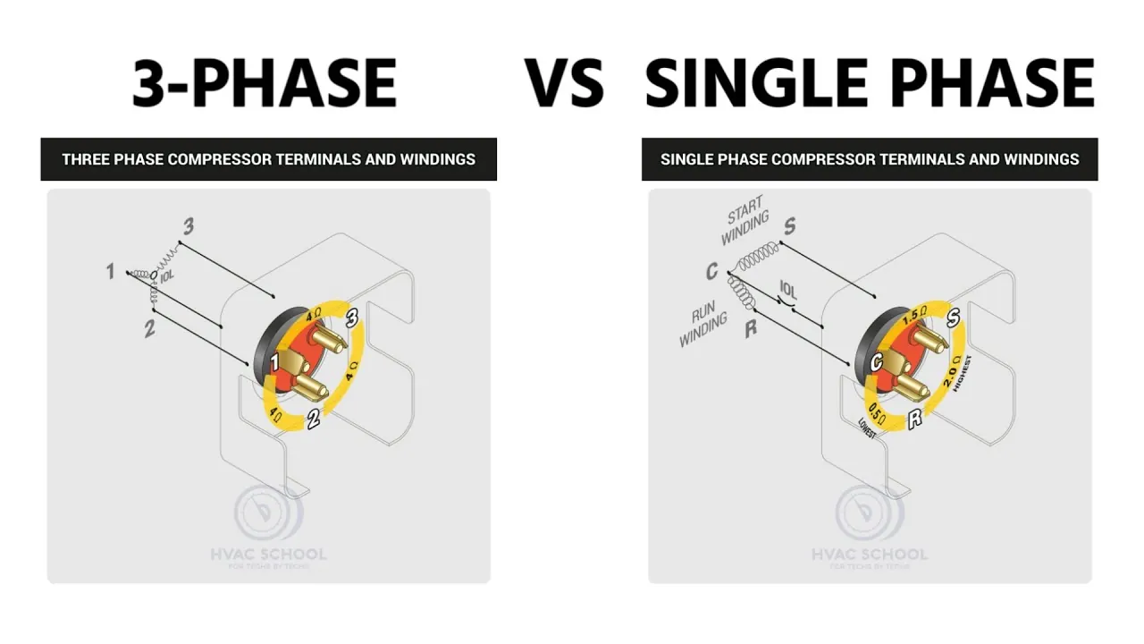
To identify the windings, you must first ensure all six motor leads are disconnected from each other and the power source. A standard three-phase induction motor contains three separate internal coils. Each coil has two ends, resulting in six leads.
To find these pairs, attach your multimeter leads to one wire and probe the remaining five. When you find a pair with a low, consistent resistance reading, you have identified one complete winding. Repeat this for the remaining four wires until you have three distinct pairs.
Understanding the Internal Coil Layout
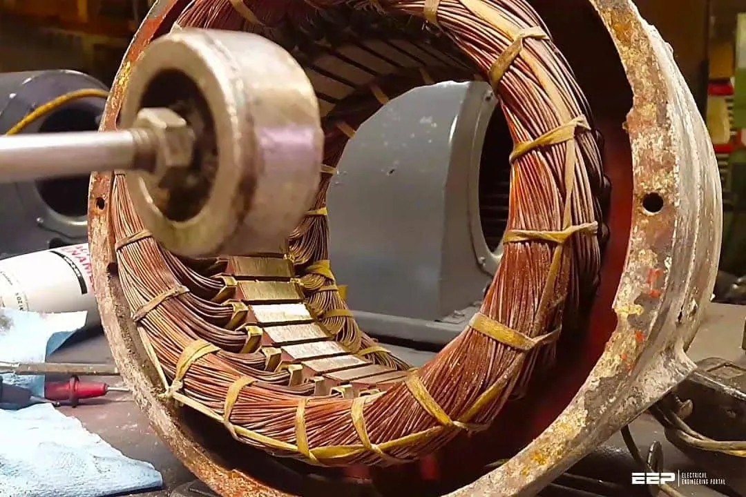
The internal architecture of these motors consists of three sets of copper coils wound around the stator slots. Each set is electrically isolated from the others. When performing your identification, look for these consistent resistance values across each pair. If the motor is healthy, the resistance should be nearly identical for all three windings. Significant deviations in the ohmic value between pairs often indicate a shorted turn or a partially burnt winding, which may necessitate professional rewinding services.
Tools Required for Testing
You don’t need specialized industrial equipment to perform basic identification. A standard digital multimeter is the primary tool used by technicians to map out internal configurations.
| Tool Name | Primary Function | Ideal Specification |
|---|---|---|
| Digital Multimeter | Measuring resistance | Accuracy within 0.5% |
| Electrical Tape | Labeling leads | High-tack adhesive vinyl |
| Wire Markers | Permanent identification | Heat-shrink or clip-on |
| Insulated Screwdriver | Terminal box access | Rated for 1,000 volts |
Safety Protocols During Testing
Warning: Never attempt testing while the motor is connected to a live power source, as back-feed voltages can cause severe injury or damage your multimeter. Before starting, verify the absence of voltage using a non-contact voltage tester or a calibrated voltmeter. Always follow your facility’s Lockout/Tagout (LOTO) procedures to ensure the energy source remains isolated throughout the duration of your winding identification task.
Step-by-Step Winding Grouping
- Isolate the motor leads and ensure they aren’t touching each other or the metal motor housing.
- Set your multimeter to the lowest resistance setting, typically the 200-ohm range.
- Select one lead and label it “1” for reference.
- Probe the other five leads one by one. The lead that shows a low resistance reading is the other end of the first coil.
- Label this pair as “1” and “4” (or Start/Finish).
- Repeat the process for the remaining four leads to identify the second pair (2 and 5) and the third pair (3 and 6).
Troubleshooting Winding Faults
If you encounter unexpected readings, the motor may suffer from internal degradation. A reading of “OL” (Open Loop) across a pair suggests a broken wire within the winding. Conversely, a reading near zero indicates a dead short, which is a common failure mode in older or overloaded units.
Distinguishing Between Wye and Delta
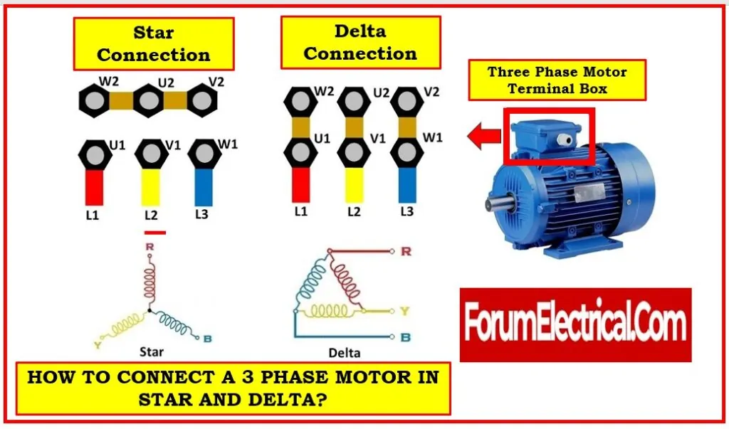
Once you have identified your three pairs, you must determine the intended configuration. A Wye connection (Star) joins one end of all three windings to a common neutral point, while a Delta connection links the end of one winding to the start of the next in a loop. You can determine the configuration by checking the motor nameplate, which typically dictates the required voltage for each setup.
| Configuration | Connection Pattern | Typical Voltage Level |
|---|---|---|
| Wye (Star) | Three ends joined together | Higher voltage (e.g., 460V) |
| Delta | Series loop of windings | Lower voltage (e.g., 230V) |
Verifying Insulation Integrity
Beyond identifying the windings, you must ensure the insulation between the copper wire and the motor frame is intact. This is known as a “megger” test or an insulation resistance test.
Use an insulation tester to apply a higher voltage (typically 500V DC) between one winding lead and the metal frame. A healthy motor should show high resistance in the mega-ohm range. If the resistance drops significantly, the winding insulation has failed, and the motor shouldn’t be put back into service.
Proper Lead Labeling Techniques
Once identification is complete, use durable markers to prevent future confusion. Standard practice involves using numbered heat-shrink tubing that corresponds to the motor terminal diagram found on the inside of the junction box cover. Avoid using masking tape or pen marks, as these degrade quickly in the high-heat environment of a running motor. Organized lead management saves hours of diagnostic time during future maintenance cycles or motor replacements.
Related guides
- Cuisinart Grinder Not Working: Simple Fixes for Motor Issues
- Momcozy M5 Motor Not Working: Simple Fixes and Troubleshooting
- Faucet Cartridge vs Faucet Aerator: How to Identify the Fix in 2026
Frequently Asked Questions
What happens if I connect the motor incorrectly?
Connecting windings in the wrong sequence or configuration can cause the motor to draw excessive current, overheat rapidly, or produce insufficient torque. In many cases, an incorrect phase sequence will cause the motor to rotate in the opposite direction, which can damage driven equipment like pumps or fans. If a motor hums but fails to turn, disconnect power immediately to prevent winding burnout.
Can I identify windings without a meter?
It isn’t possible to safely or accurately identify motor windings without a multimeter or ohmmeter. While some technicians might attempt to use a battery and compass to detect magnetic fields, this method is unreliable and risks damaging the internal insulation of the motor. Always use calibrated electrical measurement tools to ensure the windings are grouped correctly before applying any power to the unit.
Why is my resistance reading fluctuating?
Fluctuating resistance readings are often caused by poor probe contact at the terminal ends. Ensure the wire tips are clean and free of oxidation, paint, or varnish. If the reading continues to jump, your multimeter leads might be damaged, or there may be a loose connection inside the terminal block itself. Always ensure a solid, stable connection before recording your final measurement values for each winding pair.
Does the age of the motor matter?
Older motors often have brittle, cracked insulation that can cause intermittent shorts. While the identification process remains the same, older units require a more rigorous insulation resistance test. If you’re working on a motor that’s more than twenty years old, be extremely cautious when manipulating the leads, as the internal winding wire can snap easily if the insulation has become excessively hardened or degraded.
How do I identify the start and finish of a coil?
For simple identification, the start and finish of a coil are interchangeable. However, for phase rotation, orientation matters. To check polarity, you can use a low-voltage DC source and a voltmeter to observe the “kick” or pulse generated when the circuit is broken. This ensures that the magnetic fields of the three windings are properly aligned, preventing destructive interference that would otherwise prevent the motor from running smoothly.
What should I do if my motor has nine leads?
A nine-lead motor is designed for dual-voltage operation and contains more complex internal connections. These motors are typically wired in either a series-wye or parallel-wye configuration. You’ll need to consult the specific wiring diagram provided by the manufacturer or the motor nameplate to correctly identify which leads correspond to which internal winding segments. Don’t attempt to guess the wiring, as this could cause a catastrophic electrical failure.
Conclusion
After successfully identifying and labeling your motor windings, verify your connections against the manufacturer’s terminal diagram one final time before applying power. If you’re uncertain about the internal health of the motor, consult a professional motor repair shop to perform a surge test or a full winding analysis. Taking the time to double-check your work now will prevent costly repairs and ensure the longevity of your equipment.
