
A variable frequency drive controls an AC motor’s speed by changing the power’s frequency and voltage. It saves energy, cuts mechanical wear, and gives you precise control over pumps, fans, and conveyors. The numbers in this article cover standard low-voltage units under 50 horsepower. What follows explains how to size, wire, program, and protect these drives without burning out your equipment.
A complete guide to how variable frequency drives work
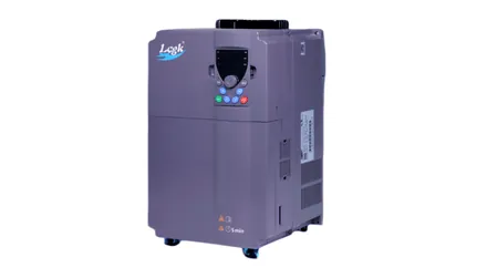
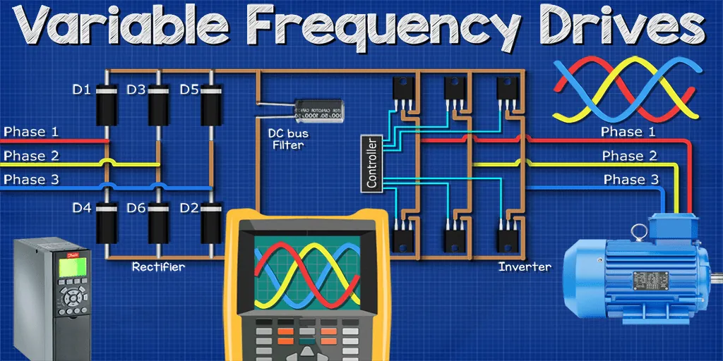
A variable frequency drive is an electronic controller that sits between your power supply and an AC motor. It converts incoming AC power to DC, then switches it back to AC at whatever frequency and voltage the motor needs right now. You use it when a motor doesn’t need to run at full speed all day.
Factories, water plants, and HVAC systems rely on them to match output to real demand. If your pump only needs half flow, the drive slows the motor instead of choking the pipe with a valve.
People often think a VFD just turns a motor on softly. That’s one feature, but its main job is continuous speed control during normal running. The relationship is roughly linear: halving the frequency halves the motor’s synchronous speed, though actual shaft speed will be slightly lower due to slip. Check your motor’s nameplate for its rated frequency before setting parameters.
How to set up a variable frequency drive
Getting a drive running means matching the hardware to the motor, wiring it safely, and entering the right numbers into the keypad. Follow these steps in order.
- Read the motor nameplate for voltage, full-load amps, and base frequency. Write these down.
- Pick a drive rated for your motor’s horsepower and current. If the load is heavy, like a rock crusher, choose one size larger than the motor’s rating.
- Mount the drive vertically on a flat metal panel. Leave at least 4 inches of clear space above and below for cooling air.
- Run the power cable through a conduit to the drive’s input terminals (L1, L2, L3). Torque the screws to the value printed inside the manual’s wiring chapter.
- Connect the motor leads to the output terminals (U, V, W). Keep output cables under 100 feet unless you install a line reactor.
- Wire a ground conductor from the panel’s ground bus to the drive’s PE terminal.
- Power up and enter the motor’s voltage, amps, and frequency into the parameter menu.
- Run the auto-tune routine so the drive measures the motor’s internal resistance.
The single judgment call here is sizing. If your load has high starting torque, buy the next size up.
Variable frequency drive settings at a glance
These are the baseline figures for common low-voltage applications. Your specific setup will change some of them, so treat this table as a starting point rather than a strict rule.
| Situation | What to use | How long | What to watch for |
|---|---|---|---|
| Standard centrifugal pump | V/Hz control mode | 10-second ramp up | Motor overheating at low speeds |
| Constant-torque conveyor | Sensorless vector mode | 5-second ramp up | Drive tripping on overcurrent |
| Cooling tower fan | V/Hz with skip frequency | 15-second ramp up | Panel shaking at 30 Hz |
| Heavy rock crusher | Oversized drive, vector mode | 30-second ramp up | DC bus overvoltage faults |
| Small 1 HP blower | Basic V/Hz mode | 3-second ramp up | High-pitched motor whine |
Always check the manufacturer’s installation manual for the exact acceleration times they recommend for your frame size. A 5-horsepower unit handles a 5-second ramp easily, but that same time might trip a 50-horsepower drive on overcurrent. Adjust the ramp time upward if the drive faults during startup.
Getting reliable results from a VFD
Heat kills electronics faster than anything else. A drive mounted inside a closed cabinet without airflow will fault on hot days and fail early. Leave ventilation space around the heatsink fins, or add a filtered exhaust fan to the enclosure.
Cable routing matters just as much. Running the motor cable in the same tray as your sensor wires invites electrical noise. Keep them at least 12 inches apart. If they must cross, make them cross at a 90-degree angle. Shielded motor cable prevents radio interference from reaching nearby instruments.
Don’t ignore the environment.
Troubleshooting VFD problems
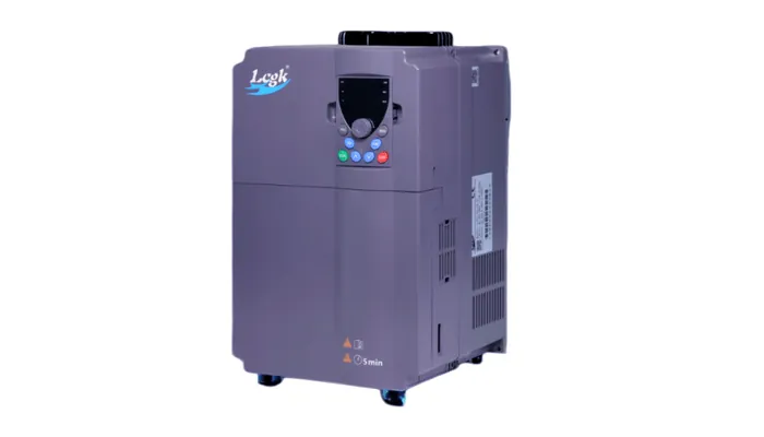
When a drive stops working, the display usually shows a fault code. Match what you see to the likely cause before resetting it blindly. Resetting a fault without fixing the root problem will damage the motor or the drive itself.
| What you notice | What it usually means | What to do first |
|---|---|---|
| Overcurrent fault (OC) | Mechanical jam or too-fast acceleration | Disconnect motor and spin shaft by hand |
| Overvoltage fault (OV) | Load pushing motor during deceleration | Increase the deceleration time setting |
| Drive screen is dead | Blown input fuse or lost phase | Check incoming voltage with a meter |
| Motor hums but won’t turn | Wrong V/Hz ratio or bad cable | Verify nameplate data in parameters |
| Drive runs, motor gets hot | Running too slow without extra cooling | Add a separate fan to the motor shaft |
If the drive trips repeatedly after you’ve checked these items, stop testing it.
Safety and electrical codes
You can’t install a drive wherever you want. The National Electrical Code (NFPA 70) requires proper overcurrent protection and disconnecting means for every motor circuit.
Drives store dangerous voltage in their DC bus capacitors even after you pull the plug. Wait at least five minutes after removing power, then measure the DC bus terminals with a voltmeter before touching any screw. If you don’t know how to verify zero energy state, leave the panel closed and call a qualified industrial electrician.
Maintaining the drive long-term
Once the system is running smoothly, it still needs attention.
The DC bus capacitors dry out over time. You’ll notice this when the drive starts tripping on undervoltage faults during normal operation.
Keep a logbook inside the panel door. Write down any parameter changes you make, along with the date and the reason. When someone else troubleshoots the machine later, that log saves hours of guessing.
When a VFD is the wrong choice
Not every motor needs one, and putting a drive on the wrong application wastes money while creating new headaches. Here’s where you should look elsewhere.
For fixed-speed applications, a contactor and overload relay are cheaper and more reliable. Adding a drive here just introduces parts that can break.
Standard AC motors running below 20 Hz lose their own cooling airflow. If your process demands constant torque at very low speeds, you’ll burn the motor out. Buy a dedicated inverter-duty motor with an independent cooling fan instead.
For extremely precise positioning, like a CNC milling machine, a servo drive is the right tool. A standard VFD lacks the feedback resolution needed to hold a position within fractions of a millimeter.
Related guides
Frequently asked questions
Can a VFD run a single-phase motor?
No, standard drives are built for three-phase AC motors. Single-phase motors use start capacitors and centrifugal switches that conflict with a drive’s output. You can use a VFD to convert single-phase wall power to run a three-phase motor, but the motor itself must be three-phase.
How much energy does a VFD save?
It depends entirely on the load type. For centrifugal pumps and fans, slowing the motor by 20% cuts power use by nearly half. For constant-torque loads like conveyors, the savings are much smaller because the current stays roughly the same regardless of speed.
Why does my motor buzz loudly on a VFD?
The drive uses high-speed switching to create its output waveform. This rapid pulsing vibrates the motor’s laminations, causing a buzzing sound. Increasing the carrier frequency parameter reduces the noise, but it also increases heat inside the drive, so there’s a trade-off.
Is it safe to put a switch between the VFD and motor?
No, breaking the connection while the drive is outputting power causes severe voltage spikes that destroy the output transistors. If you need a disconnect switch for maintenance, wire it on the input side of the drive, or ensure the drive is fully stopped before opening the output switch.
How long does a variable frequency drive last?
Expect a long service life in a clean, cool environment with stable power. Heat and dirty power shorten that lifespan significantly. You can estimate the drive’s usage by checking the runtime counters in the drive’s diagnostic menu.
What happens if the power drops out briefly?
Most drives will trip on an undervoltage fault and stop the motor immediately. Some models offer a “ride-through” feature that uses the spinning motor’s momentum to generate enough power to keep the drive’s logic alive until grid power returns.
Conclusion
Every installation has its own quirks, but the physics stay the same. Size the drive for the actual load, route your cables away from sensitive signals, and write down the settings you change. That discipline keeps the motor turning and the drive out of the repair shop.
