
Relays are electrically operated switches that let a low-power circuit control a much higher-power one, usually through an electromagnet and a set of contacts.
What a relay actually is

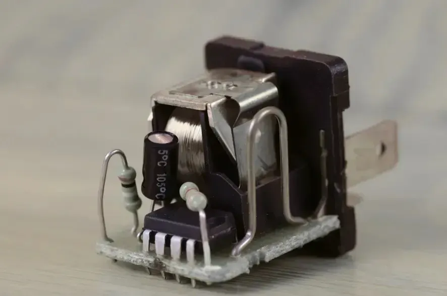
A relay is a switch that opens or closes one circuit using a signal from a separate, isolated circuit. Most relays use an electromagnet: when current flows through the coil, it pulls an armature that moves the contacts, turning a load such as a motor, lamp, or heater on or off. They’re used in cars, home appliances, industrial controls, and electronics wherever a small signal must drive something that draws more power than a microcontroller or switch can safely handle.
The key misconception is that a relay amplifies power. It does not. It isolates and controls; the power still comes from the load’s own supply. A relay typically has a coil side rated for a specific voltage, and a contact side rated for a maximum voltage and current that should be verified by a professional.
Choosing the right relay
Pick a relay by matching four ratings to your circuit, not by guessing at size. First, check the coil voltage your control signal can provide — common options are available in various DC ratings. Second, confirm the contact rating exceeds your load’s voltage and current, with margin for startup surges.
Third, choose the contact form: normally open (NO) closes when energized, normally closed (NC) opens when energized, and changeover switches between two circuits. Fourth, decide if you need a diode across the coil to suppress the spike that appears when the coil turns off, a task best handled by a technician to ensure the circuit is protected from damage.
- Read your load’s voltage and current draw from its nameplate or manual.
- Select a relay whose contact rating is at least 25 percent above that load.
- Match the coil voltage to your control circuit’s output.
- Mount the relay so its terminals can’t touch metalwork or other wires.
- Connect the coil to your control signal through a switch or transistor output.
- Connect the load supply to the common contact and the load to the NO or NC contact.
- Add a flyback diode across the coil if a semiconductor switches the coil.
The single judgement call is contact rating versus real load. A motor or lamp can draw several times its running current at startup, so a relay sized only for running current will weld its contacts shut or burn out.
Check the load’s inrush current, not just its steady rating, before you finalize the choice. If the load is mains voltage or the coil is driven by a circuit you didn’t design, have someone qualified check the wiring before power is applied.
Relay ratings and settings at a glance
| Situation | What to use | How long | What to watch for | | 12 volt car accessory | 12 volt coil, 30 or 40 amp NO relay | Continuous while switched | Coil current draw on the control circuit | | 5 volt microcontroller output | 5 volt coil relay with flyback diode | Pulsed or continuous | Diode polarity; transistor base current | | Mains lamp or heater | Relay rated for 120 or 240 volts AC | Continuous while switched | Contact rating above load inrush | | Reversing a small DC motor | Double-pole changeover relay | Intermittent | Wiring both poles so the motor can’t short | | High-cycle industrial output | Solid-state relay instead of mechanical | Continuous or rapid cycling | Heat buildup; minimum load current |
These figures assume room temperature and a resistive load unless noted. Inductive loads such as motors and solenoids cut usable contact life sharply, so derate accordingly or choose a relay built for inductive switching.
What makes a relay last
Good results come from preparation and checking, not from buying the most expensive part. Experienced users derate contacts for inductive loads because a motor or solenoid can draw many times its running current at startup, and the arc at switch-off eats contacts quickly. They check the coil resistance before wiring so an open or shorted coil is caught early, not after installation.
They verify contact continuity with a multimeter after the first few operations, and they leave the coil voltage alone once the relay is energized — changing it mid-cycle causes chatter and welded contacts. They also keep load wiring short and tight, since loose connections create heat at the terminals.
Problems and what to do about them

| What you notice | What it usually means | What to do first | | Relay clicks but load doesn’t work | Contacts burnt, welded, or wrong terminal | Test contact continuity with a multimeter | | No click when coil energized | Open coil, wrong coil voltage, or no control voltage | Measure coil voltage with the control signal on | | Contacts stick closed after use | Overload or inrush welded the contacts | Replace the relay and derate for the load | | Control transistor fails when coil turns off | Missing flyback diode | Add a diode across the coil, cathode to positive |
If the relay chatters — clicking rapidly instead of holding steady — the control voltage is too low or the power supply can’t hold it under load. Measure at the coil terminals while energized; if the voltage sags, stiffen the supply before anything burns.
Rules and limits that matter
Relay contact ratings are maximums, not recommendations, and exceeding them voids any manufacturer warranty and can cause contact failure or fire. For automotive relays, ISO 7637 covers electrical transients in vehicle systems, and relay makers publish derating charts for inductive and capacitive loads.
The National Electrical Code, published by the National Fire Protection Association, governs how control wiring and load circuits must be separated and protected in fixed installations. Where a job involves mains wiring, a vehicle’s safety systems, or equipment under warranty, have the work checked by a qualified electrician or technician before it’s energized.
Keeping a relay installation working
Once installed, a relay needs little attention, but it isn’t fit-and-forget. Check the contact terminals for discoloration or looseness at regular intervals, and listen for chatter or buzzing that signals a failing coil or weak supply. In dusty or vibrating environments, inspect more often because contamination and movement wear contacts faster.
There’s no universal replacement interval; the deciding factor is the number of operations and the load type, which the manufacturer’s datasheet lists as mechanical and electrical life. Replace a relay when contacts no longer close cleanly or when the coil resistance reads far outside its marked value. If you’re unsure of the rating for your specific model, check the manufacturer’s own datasheet rather than guessing.
When a relay is the wrong choice
A mechanical relay isn’t right for every job. If you need to switch more than a few times per second, contact wear and bounce make it unsuitable; use a solid-state relay or a transistor instead. If the load draws only a small current and space is tight, a MOSFET or transistor module takes less room and has no moving parts.
If the circuit must fail-safe when power is lost, remember that a normally open relay opens with the coil — choose a normally closed unit or add external logic. These alternatives cost more or add complexity, so use them only when the relay’s limits actually apply.
Frequently asked questions
Can a relay control AC and DC at the same time?
No. Use separate relays or a relay rated for both, because AC and DC contact ratings differ and mixing them on one contact set can cause arcing and early failure.
Why does a relay need a diode across the coil?
When the coil turns off, its magnetic field collapses and creates a high-voltage spike that can destroy the transistor or output driving it; the diode gives that spike a safe path.
How long do relay contacts last?
Mechanical life is often millions of operations, but electrical life under load is much lower and depends on the load type; check the manufacturer’s datasheet for the exact figure for your model.
Is it safe to wire a relay to mains voltage?
Only if the relay is rated for that voltage and current and the installation follows the National Electrical Code; otherwise have a qualified electrician do the work.
What happens if the coil gets the wrong voltage?
Too low and the relay chatters or doesn’t pull in; too high and the coil overheats and fails. Match the coil voltage exactly to your control supply.
How do I know which contact is normally open?
With the coil unpowered, measure between common and each contact with a multimeter; the pair showing infinite resistance is normally open.
Conclusion
Relays remain one of the most useful ways to isolate and control power, but they only do their job when the coil voltage, contact rating, and load type are matched correctly. Choose the rating for the real load, protect the driving circuit from coil spikes, and check the installation before you rely on it.
