
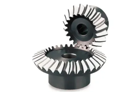
Straight bevel gears are mechanical components featuring teeth cut into a conical surface, designed primarily to transmit power between intersecting shafts, most commonly at a 90-degree angle. These gears consist of a truncated cone shape where the teeth taper toward the apex of the cone, allowing them to mesh smoothly while changing the direction of rotational force within a machine. By utilizing a simple, robust geometry, they provide a reliable method for redirecting torque in everything from hand-operated drills to heavy-duty industrial machinery.
Key Takeaways
- Straight bevel gears are best suited for low-speed applications due to their tendency to generate noise at high velocities.
- Always ensure precise shaft alignment during installation, as even minor misalignments significantly accelerate tooth wear.
- Regular lubrication using high-pressure grease or oil is essential to prevent metal-to-metal contact and surface pitting.
- When selecting gears, match the pressure angle—typically 20 degrees—to ensure compatibility with existing drive systems.
- Prioritize hardened steel or case-hardened alloys for high-load environments to maintain structural integrity over time.
What Are Straight Bevel Gears?
Straight bevel gears represent the most basic form of bevel gearing. Unlike helical or spiral bevel gears, the teeth on these components are straight and parallel to the axis of the cone. When two of these gears mesh, their pitch cones roll against each other without slipping, provided the teeth are correctly engineered.
Because the teeth are straight, the contact occurs across the entire length of the tooth simultaneously, which creates a distinct “click” or vibration during operation. This characteristic limits their application to scenarios where speed and silence aren’t the primary engineering constraints.
How Do These Gears Work?
The fundamental operation of these gears relies on the geometry of intersecting pitch cones. As the driving gear rotates, its teeth push against the teeth of the driven gear, forcing the driven gear to rotate around its own axis. Because the shafts are typically positioned at a 90-degree angle, the input torque is redirected perpendicularly.
The mechanical advantage is determined by the ratio of the number of teeth on the gear to the number of teeth on the pinion. If the pinion has 10 teeth and the gear has 40, the system provides a 4:1 gear reduction, increasing torque while reducing rotational speed.
| Feature | Straight Bevel Gear | Spiral Bevel Gear |
|---|---|---|
| Tooth Geometry | Straight, non-curved | Curved, oblique |
| Noise Profile | High at speed | Low and smooth |
| Load Capacity | Moderate | High |
| Manufacturing Cost | Relatively low | Higher |
Common Applications and Uses
You’ll find these gears in a variety of mechanical systems where simple, cost-effective motion transfer is required. They’re frequently utilized in:
- Hand-operated tools such as manual drills.
- Differential drives in basic agricultural equipment.
- Valve actuators used in piping systems.
- Printing presses requiring synchronized rotation.
- Food processing machinery for simple mixing tasks.
Materials Used for Construction
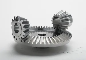
The durability of a gear depends heavily on the material chosen during the manufacturing process. Manufacturers often select materials based on the specific load and environmental conditions the gear will face. Common choices include:
- Carbon Steel: Frequently used for general-purpose applications where cost is a factor.
- Alloy Steel: Preferred for high-stress environments where fatigue resistance is critical.
- Cast Iron: Sometimes utilized in low-speed, high-vibration scenarios for its damping properties.
- Nylon or Delrin: Often selected for light-duty, non-lubricated applications in consumer goods.
- Stainless Steel: Used in food or chemical industries to prevent corrosion.
Why Is Installation Accuracy Critical?
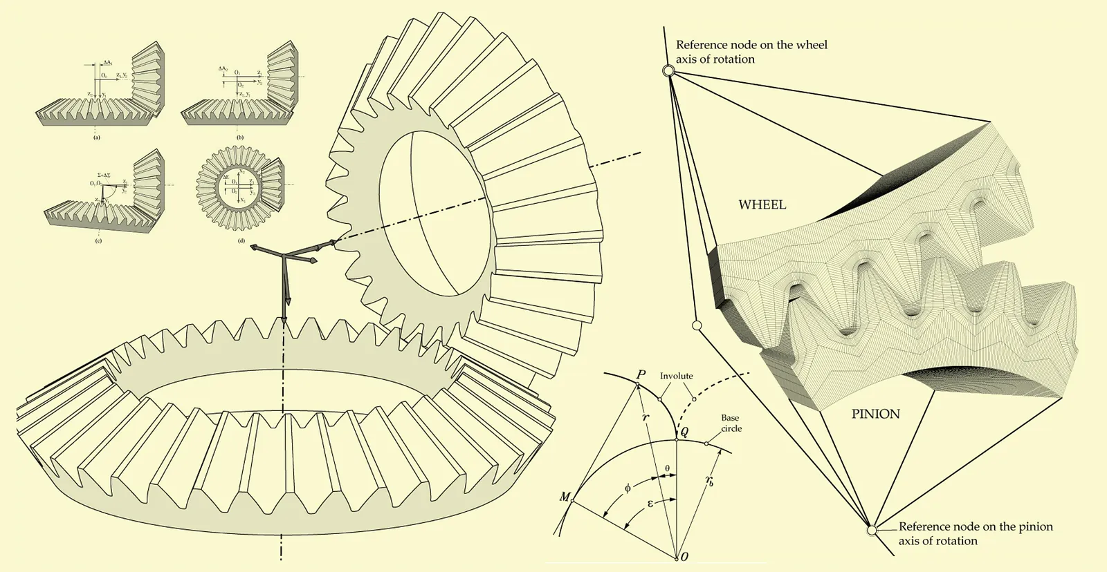
Warning: Improper shaft mounting can lead to catastrophic gear failure. When installing straight bevel gears, the apexes of the two pitch cones must coincide exactly at the intersection point of the shafts. If the shafts are slightly offset or skewed, the teeth will engage unevenly, causing point loading on the corners of the teeth. This concentration of force leads to chipping, cracking, and premature fatigue.
Factors Affecting Gear Performance
Several technical factors dictate how well a gear set will perform in a real-world assembly. Engineers must carefully balance these variables to avoid mechanical failure.
The Role of Pressure Angle
The pressure angle is the angle at which the teeth exert force on one another. A 20-degree pressure angle is the industry standard for straight bevel gears, offering a balance between tooth strength and smooth engagement. Lower angles can result in undercut teeth, while higher angles increase the radial force on the bearings.
Managing Backlash
Backlash is the clearance between meshing teeth. In straight bevel gears, a small amount of backlash is necessary to allow for thermal expansion and lubrication. However, too much backlash leads to impact loading, especially during frequent starts and stops.
Maintenance and Troubleshooting
Maintaining your gear system is straightforward if you follow a consistent schedule. Proper care extends the service life of the gears significantly.
| Maintenance Task | Frequency | Action Required |
|---|---|---|
| Visual Inspection | Monthly | Check for metal shavings or wear |
| Lubrication Check | Weekly | Verify grease or oil levels |
| Alignment Check | Quarterly | Ensure shafts remain at 90 degrees |
| Noise Assessment | Daily | Listen for grinding or abnormal clicks |
Pro Tip: Regular oil analysis can reveal microscopic metal particles long before a gear fails, allowing for proactive replacement during scheduled downtime rather than emergency repairs.
How to Select the Right Gear
When purchasing or designing a system, look for these specific indicators of quality:
- Tooth Profile: Ensure the teeth are cut to a standard involute profile for consistent motion.
- Surface Finish: Look for ground or polished teeth to reduce friction.
- Hardness Rating: Check for case-hardened surfaces to resist abrasive wear.
- Mounting Configuration: Verify the hub style, such as keyway or set screw, fits your drive shaft.
Common Mechanical Failures
Even with proper maintenance, gears can fail due to unforeseen stresses or environmental factors. Recognizing these signs early is crucial:
- Pitting: Small craters on the tooth surface caused by high contact stress.
- Spalling: Large flakes of metal breaking away from the surface due to fatigue.
- Scuffing: Surface damage caused by inadequate lubrication leading to localized welding.
- Tooth Breakage: Sudden failure often caused by shock loads or excessive torque beyond design limits.
Frequently Asked Questions
Can straight bevel gears run at high speeds?
Straight bevel gears are generally not recommended for high-speed applications because the sudden engagement of the entire tooth length generates significant noise and vibration. For high-speed systems, spiral bevel gears are preferred as their curved teeth allow for a gradual, continuous contact transition, which significantly reduces noise levels and improves the overall smoothness of the power transmission.
What is the standard angle for these gears?
While they can be manufactured for various angles, the vast majority of straight bevel gears are designed for a 90-degree shaft intersection. This specific configuration is the standard for most industrial gearboxes, manual tools, and general mechanical drives. If your application requires a non-standard angle, the gears must be custom-cut to match the specific pitch cone angles required for the intersection.
How do I reduce noise in a gear system?
To minimize noise, ensure the gears are perfectly aligned and have the correct amount of backlash. Using a high-quality, vibration-dampening lubricant can also help. If the noise persists, it may be a design limitation of the straight-cut teeth, and you might need to consider switching to a helical or spiral bevel design, which provides much quieter operation due to the gradual tooth engagement.
Should I use oil or grease for lubrication?
The choice between oil and grease depends on the speed and enclosure of the gear system. Oil is typically better for high-speed, enclosed gearboxes as it provides better cooling and distribution. Grease is often preferred for slower, open-air, or lightly loaded systems because it stays in place longer and requires less frequent maintenance, effectively preventing metal-to-metal contact over extended periods.
Why do the teeth wear out unevenly?
Uneven wear usually indicates a misalignment of the shafts or an incorrect mounting distance. If the pitch cones don’t meet perfectly at the apex, one side of the tooth will carry more load than the other. This concentrated pressure causes rapid material degradation. Always verify that your shaft supports are rigid and that the gears are shimmed to the exact mounting distance specified by the manufacturer.
Conclusion
To ensure your mechanical systems operate reliably for years, begin by inspecting your current gear alignment to confirm that the shafts meet at the exact 90-degree intersection required for your specific gear set. If you detect any vibration or abnormal noise, consult your equipment manual to verify the recommended lubrication interval and adjust your maintenance schedule to prevent premature wear.
