
Types of testing equipment used in electrical engineering include multimeters, insulation resistance testers, clamp meters, earth ground testers, power quality analyzers, and high-potential testers. These tools check voltage, current, insulation, grounding, and power quality to keep electrical systems safe and working. What separates them is what each one measures and the conditions under which it’s used.
Types of testing equipment used in electrical engineering

Every item below measures something specific about an electrical system, and none of them can stand in for another.
| What it’s called | What it’s best for | One example |
|---|---|---|
| Multimeter | Voltage, current, resistance | Fluke 87V |
| Clamp meter | Current without breaking the circuit | Fluke 325 |
| Insulation resistance tester | Checking insulation condition | Megger MIT400 |
| Earth ground tester | Verifying grounding systems | Fluke 1625 |
| Power quality analyzer | Tracking voltage and power issues | Fluke 435 |
| High-potential tester | Testing insulation under high voltage | Megger S1 |
Multimeter
A multimeter measures voltage, current, and resistance in one handheld tool. It suits anyone working on circuits, panels, or wiring who needs fast readings. It’s good for checking battery voltage, testing continuity in a wire, measuring resistance in a component, and confirming that a circuit is de-energized before work begins.
A digital display shows the number, and a dial selects the function and range. A technician uses one to check a standard 120-volt outlet before plugging in equipment. Set the dial to the correct function before touching the probes to anything.
Clamp meter
A clamp meter measures current by clamping around a wire instead of touching it directly. It suits electricians who need to read current on live conductors without opening panels or breaking connections. It’s good for reading load current on a running motor, checking phase balance on a three-phase panel, and measuring inrush current when equipment starts.
The jaws open and close around a single conductor, and the display shows amps. A maintenance tech clamps it around a motor lead to confirm the draw matches the nameplate rating. Never clamp around a multi-conductor cable, because the magnetic fields cancel and the reading will be wrong.
Insulation resistance tester
An insulation resistance tester applies a high DC voltage to check whether insulation is intact or breaking down. It suits maintenance teams verifying cables, motors, and transformers before energizing equipment. It’s good for finding moisture or damage in wire insulation, confirming motor windings are sound, and checking cable runs after installation.
The tester injects voltage and measures leakage current, then reports resistance. A technician tests a 480-volt motor winding and records the result before commissioning. Always disconnect and isolate the circuit under test, because the tester’s high voltage can damage connected electronics or shock anyone touching the line.
Earth ground tester

An earth ground tester checks that grounding systems provide a safe path for fault current. It suits electrical contractors and facility staff verifying grounding rods, grids, and bonds. It’s good for measuring ground rod resistance, testing bonding between panels and ground bars, and confirming lightning protection systems work.
The tester sends a known current through ground stakes and measures the voltage drop to calculate resistance. A technician drives two auxiliary rods into soil and tests a building ground electrode, expecting a reading where code allows. Dry or rocky soil raises resistance, so seasonal changes can move the result even when the installation is unchanged.
Power quality analyzer
A power quality analyzer records voltage, current, harmonics, and transients over time. It suits engineers diagnosing flickering lights, nuisance tripping, or overheating transformers in commercial and industrial plants. It’s good for capturing voltage sags, logging harmonic distortion from variable frequency drives, and documenting events that explain equipment failures. The analyzer connects to the panel and records data for days or weeks.
A plant engineer logs a 480-volt distribution panel for two weeks to find why drives trip each morning at startup. The National Fire Protection Association publishes guidance on electrical safety in the workplace through its NFPA 70E standard. The cost of the instrument and the time needed to interpret the data mean it isn’t a first tool for routine checks.
High-potential tester
A high-potential tester, or hipot tester, applies elevated voltage to verify insulation strength under stress. It suits manufacturers and repair shops testing new or rebuilt motors, transformers, and cable assemblies before they enter service. It’s good for proving insulation can withstand temporary overvoltage, catching weak spots after a repair, and validating production units against a design specification.
The tester ramps voltage up and holds it while monitoring leakage current. A technician tests a repaired 5-kilovolt cable and watches for breakdown. This test can destroy marginal insulation, so it’s used to prove quality, not to troubleshoot a live system in service.
Other testing tools
Circuit tracer — finds the path of a concealed wire and identifies which breaker feeds it; useful when labels are missing or wrong.
Power clamp logger — records current over time on a conductor without breaking the circuit; suits load studies and billing verification.
Phase rotation tester — confirms the order of phases on a three-phase supply; needed before connecting motors that must run in a specific direction.
Battery impedance tester — measures internal resistance of battery cells without discharging them; used in UPS and substation battery maintenance.
How to choose between them
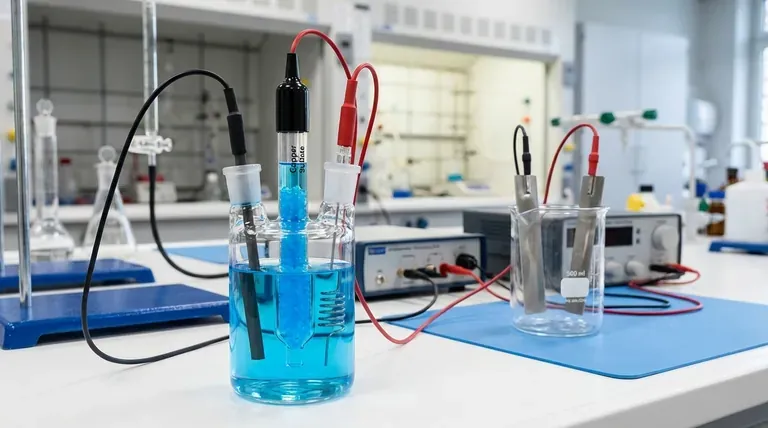
Start with what you need to measure. Voltage, resistance, and continuity point to a multimeter. Current on a live wire means a clamp meter. Insulation condition calls for an insulation resistance tester. Grounding verification needs an earth ground tester. Intermittent power problems require a power quality analyzer. Insulation proof testing needs a hipot tester. What you already own and how much time you can give the job also matter.
A clamp meter adds little cost to a kit, while a power quality analyzer costs far more and needs training to read its logs. Some tools combine functions, but buying one instrument for every task usually means leaving capabilities unused. Match the tool to the voltage level and environment you work in, and never exceed its rated category.
Frequently asked questions
Can one multimeter replace all the other testers?
No. A multimeter measures voltage, current, and resistance, but it can’t test insulation resistance, verify ground rod performance, or log power quality events over time. Each dedicated tool does something a multimeter cannot.
Why does insulation resistance drop when it gets damp?
Moisture provides a conductive path across or through insulation, so leakage current rises and measured resistance falls. Temperature also moves the reading, so corrections are often applied.
How long does a power quality study take?
It typically runs for one to two weeks, because the analyzer must capture enough normal operation and problem events to show a pattern. Shorter logs can miss the fault entirely.
Is it safe to test insulation on live equipment?
No. Insulation resistance and hipot tests require the circuit to be de-energized, isolated, and locked out. The tester injects its own voltage, and connecting it to live power can destroy the meter and injure the user.
What happens if you clamp a meter around a three-conductor cable?
The magnetic fields from the conductors cancel each other, so the meter reads near zero even when current is flowing. Clamp around one conductor only.
Does it matter which ground tester method you use?
Yes. Fall-of-potential testing needs auxiliary rods and open space, while clamp-on ground testers work where you can’t drive rods but read only loop resistance. The site conditions decide which method gives a valid number.
What to do next
Pick the tester that matches the measurement you need and the voltage level you work at. Expect a clear reading on the display, and verify it against a known source or a second reading.
If your meter shows a reading where you expect zero, treat the circuit as live regardless of the display. A common mistake is failing to check the leads for fraying or internal breaks before testing; this oversight often leads to a false negative that can cause a shock.
Stop and call a qualified electrician if the equipment is live, the panel is unfamiliar, or the test requires opening energized enclosures. If you see signs of arcing or smell ozone, leave the area immediately. Don’t attempt to reset a tripped breaker if the fault remains unknown.
