
A rosette strain gauge is a specialized sensor that measures strain in three different directions simultaneously to determine the full state of stress on a surface. It works by combining three individual strain gauge grids into a single, compact unit, which allows engineers to calculate both the magnitude and the direction of principal stresses. This setup is essential because standard single-axis gauges can only measure deformation along one line.
Components of a multiaxial sensor

The device relies on several key elements to capture precise data from a material under load. When these parts function correctly, they provide a complete picture of how a mechanical part bends or stretches. If the setup is wrong, the data will be misleading or completely inaccurate. You can verify your specific model’s requirements in the Vishay Precision Group technical notes for installation standards.
| Part or input | What it does | What you notice when it goes wrong |
|---|---|---|
| Foil grid | Converts physical stretch into electrical resistance | Readings drift or stay at zero |
| Adhesive | Bonds the gauge to the test surface | Sensor peels or gives erratic results |
| Lead wires | Carries signals to the data logger | High signal noise or broken connections |
| Protective coating | Shields the sensor from moisture | Rapid baseline shift or signal loss |
| Wheatstone bridge | Balances the resistance for measurement | Unstable output or inability to calibrate |
How a rosette strain gauge measures
To get an accurate result, you must follow a precise sequence for applying and reading the gauge. Each step impacts the final accuracy of your stress analysis.
- Clean the surface with a chemical solvent until a wipe comes away completely clear, as any remaining oil will prevent the adhesive from bonding.
- Mark the exact orientation lines on the part using a pencil, ensuring the center of the rosette aligns with the point of interest.
- Apply a thin layer of cyanoacrylate or epoxy adhesive to the back of the gauge, using only the amount specified by the manufacturer’s instructions.
- Press the gauge onto the surface with firm, even pressure for 60 seconds to ensure the adhesive cures without trapping any air bubbles underneath.
- Solder the lead wires to the terminal pads, keeping the heat application under 3 seconds per pad to avoid damaging the delicate foil grid.
- Connect the wires to your data acquisition system and perform a shunt calibration to verify that the bridge outputs match the expected resistance change.
Interpreting stress from gauge data
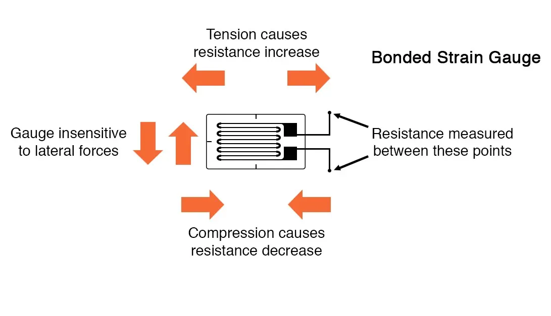
The primary purpose of using this device is to solve the problem of unknown stress directions. If you only use a single-axis gauge, you must know the exact direction of the force beforehand.
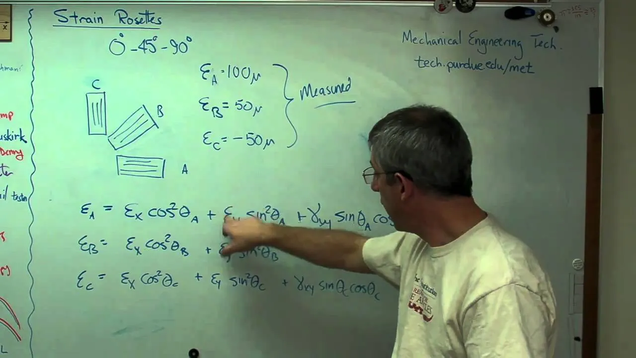
If you guess the direction wrong, your measurement will be significantly lower than the actual stress, potentially leading to a structural failure. A rosette removes this guesswork by capturing data in multiple directions, typically 0, 45, and 90 degrees or 0, 60, and 120 degrees depending on the design.
By comparing the three readings, you can use mathematical formulas to calculate the principal strains. This process tells you exactly where the material is being pulled the hardest. If you see high strain values on one grid but near-zero on the others, the force is acting in a simple, one-way direction.
If all three grids show varying values, the material is experiencing complex, multi-directional loading. This distinction is vital for safety-critical parts, such as aircraft landing gear or bridge supports. Without the rosette, you would be blind to the shear stresses that often cause cracks to form. It turns raw electrical resistance changes into a complete map of the stress state on a surface.
What you can change and what you cannot
Things you control
- The surface preparation method used before bonding.
- The type of adhesive selected for the specific material.
- The precision of the alignment with the stress axis.
- The quality of the wiring and cable shielding.
Things fixed by design
- The physical gauge factor or sensitivity constant.
- The geometric arrangement of the internal grids.
- The maximum temperature limit of the sensor base.
If your application involves high-pressure vessels or critical infrastructure, you must ensure the installation follows local engineering safety codes. Improperly installed sensors can provide false readings that lead to dangerous misjudgments of structural integrity. Always consult a licensed professional engineer if you’re working on load-bearing components where a failure could result in injury or significant financial loss.
Tips for better data collection
To get the most out of your readings, you must manage the electrical environment carefully. Temperature changes are the most common source of error; if the ambient temperature shifts by 10 degrees Celsius, the gauge might report a false strain due to thermal expansion. You should use a “dummy” gauge on a piece of the same material that isn’t under load to cancel out these thermal effects.
Always check your wire lengths, as resistance increases with distance. For runs over 10 meters, you should use a four-wire measurement setup to compensate for lead-wire resistance. Keep your data logger close to the test site to minimize interference.
If you see your signal drifting while the load remains static, check your ground loops immediately. A shared power source between your logger and an industrial motor often introduces noise that looks like real data. If the noise persists, isolate the sensor power supply from the building grid.
Finally, replace your adhesive if it has passed its expiration date. Old glue fails to transfer the full strain from the part to the sensor grid, leading to under-reported values that can cause structural fatigue models to fail.
Related guides
- Best Elevated Raised Toilet Seats to Reduce Joint Strain in 2026
- Best Water Pressure Gauges to Monitor Your Home Plumbing Health in 2026
Frequently asked questions
Can I reuse a rosette strain gauge after removing it?
No, you can’t reuse a strain gauge because the thin foil grids are permanently damaged during the removal process. The bond between the gauge and the surface is meant to be permanent, and any attempt to peel the sensor off will stretch or break the metallic tracks, rendering the device useless for future measurements.
How long does a rosette strain gauge last?
A properly installed gauge can last for many years if it remains in a controlled, dry environment. If the sensor is exposed to moisture, chemicals, or extreme vibration, the bond or the protective coating may degrade within 6 to 12 months, requiring you to replace the sensor to maintain accurate data collection.
Is it safe to install these on high-voltage equipment?
No, you should never install these gauges on live high-voltage equipment without specialized electrical isolation. The metallic foil and the lead wires can conduct electricity, creating a significant shock risk to the installer. Always de-energize and lock out any electrical systems before beginning the installation of any strain measurement equipment.
What happens if I use the wrong adhesive?
If you use the wrong adhesive, the sensor will suffer from “creep,” where the gauge slides slightly under load instead of measuring the material’s deformation. This results in a measurement that starts correctly but slowly drifts or loses signal over time, making it impossible to obtain reliable data for long-term stress monitoring.
Does the gauge orientation matter?
Yes, the orientation is the most important factor because the three grids must be perfectly aligned with the axes of your calculation model. If the rosette is rotated by even a few degrees, the mathematical transformation used to find the principal stress will yield incorrect values, leading to a faulty analysis of the stress state.
How many wires do I need for a rosette?
Connecting a full 3-grid rosette to a data logger typically requires 4 wires for a quarter-bridge configuration, though specific setups may vary. While some setups use common ground wires to reduce this to 6 or 7, you must consult the manufacturer’s wiring diagram to ensure signals remain properly isolated.
Conclusion
Choosing the right layout for your specific application is the most important part of the process. Once you’ve selected the correct pattern for your material, you’ll be ready to start your measurements with confidence. It’s a great way to ensure your structures stay safe and perform exactly as they should.
