
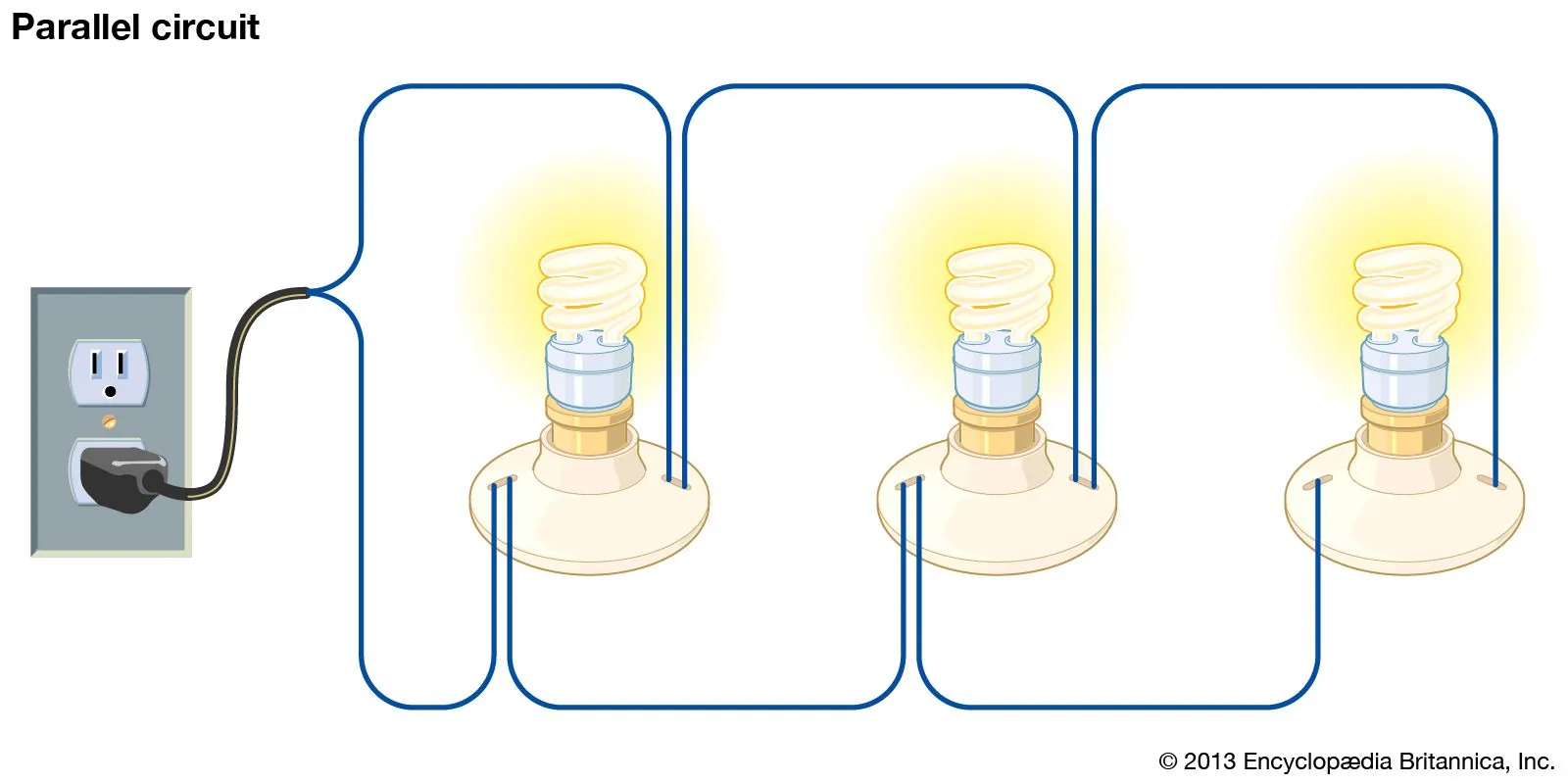
A parallel circuit is an electrical wiring arrangement where components connect across the same two nodes, creating multiple independent paths for current to flow. If one path breaks, electricity continues traveling through the remaining branches without interruption.
Key Takeaways
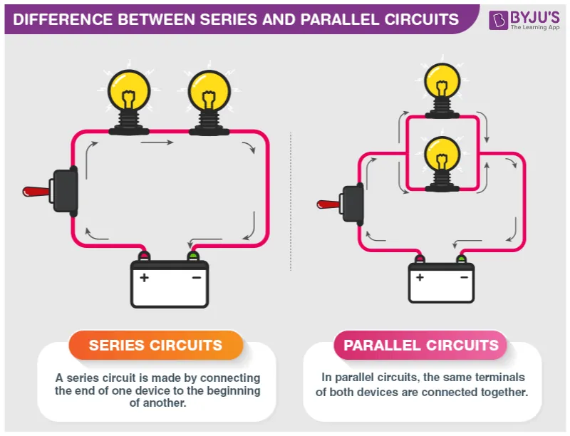
- Components in a parallel layout share the exact same voltage drop, ensuring uniform power delivery to every branch.
- Total resistance decreases as you add more branches, calculated using the reciprocal formula rather than simple addition.
- A single burned-out bulb or broken wire doesn’t interrupt power to other devices on the same network.
- The total current drawn from the source equals the sum of the currents flowing through each individual branch.
- Household wiring uses this topology so that plugging in a toaster doesn’t dim your overhead lights.
- Always calculate total amperage before adding new loads to prevent tripping breakers or overheating wires.
What Is a Parallel Circuit?
A parallel circuit routes current through multiple independent branches. Unlike series layouts, every device connects directly to the power source. Each component receives the full supply voltage. When electrons leave the negative terminal of a battery, they split at a junction, travel through various components, and recombine before returning to the positive terminal.
Engineers rely on this principle to design reliable systems where individual component failure doesn’t cause catastrophic system shutdowns. You see this architecture everywhere, from the wiring inside a desktop computer to the lighting grid in a commercial office building.
How Does Current Flow?
Current behaves differently here than in series arrangements. At any junction point, the total amperage divides among available branches based on their individual resistance values. A branch with lower resistance draws more current, while a higher-resistance branch draws less. However, the voltage remains constant across every single branch. Electrons follow the same logic. Each appliance operates on its own dedicated branch, drawing only the current it requires from the shared voltage source.
Calculating Total Resistance
Calculating total resistance requires a specific formula. You can’t simply add resistor values together. Instead, you use the reciprocal formula: one divided by the total resistance equals the sum of the reciprocals of each individual branch resistance. For two resistors, a shortcut exists called the product-over-sum method. You multiply the two values together and divide by their sum. Adding more branches always lowers the total equivalent resistance, meaning the power source must deliver more total current.
| Resistor Configuration | Formula Used | Example Values | Resulting Resistance |
|---|---|---|---|
| Two Equal Resistors | Value divided by two | Two 10-ohm resistors | 5 ohms |
| Two Unequal Resistors | Product over sum | 6 ohms and 3 ohms | 2 ohms |
| Three or More | Reciprocal sum formula | 12, 6, and 4 ohms | 2 ohms |
This inverse relationship means that adding a high-resistance component still slightly reduces the overall network resistance.
Voltage Behavior Across Branches
One of the most important rules in electrical theory is that voltage is identical across all components wired in parallel. Whether you measure across a tiny indicator light or a heavy-duty motor connected to the same two nodes, your multimeter will display the same reading.
This happens because each component bridges the exact same potential difference provided by the source. If the voltage dropped across each successive device like it does in a series string, only the first appliance would function correctly.
Parallel vs Series Circuits
Comparing these topologies helps troubleshoot and design systems. Series circuits force current through a single path, meaning one failure stops everything. Parallel circuits offer redundancy and independent operation.
| Feature | Parallel Circuit | Series Circuit |
|---|---|---|
| Current Path | Multiple independent branches | Single continuous loop |
| Voltage Distribution | Same across all components | Divided among components |
| Component Failure Effect | Others continue working normally | Entire circuit loses power |
| Total Resistance | Decreases as branches are added | Increases as components are added |
| Common Application | Home wiring, automotive lighting | Old holiday lights, basic switches |
The choice between them depends entirely on the application requirements.
Why Homes Use Parallel Wiring
Homes use parallel architecture for safety and functionality. By wiring outlets and fixtures in parallel, electricians ensure every receptacle delivers a full 120 volts (or 240 volts for large appliances). If a short circuit occurs in the bathroom, only that specific breaker trips, leaving the rest of the home powered. The National Electrical Code mandates specific wire gauges and breaker ratings to handle the cumulative current safely.
Real World Applications
This topology appears in many everyday technologies. Automotive electrical systems wire headlights, taillights, dashboard indicators, and power windows in parallel so a blown headlight bulb doesn’t disable your brake lights. Computer motherboards distribute power to USB ports, RAM slots, and PCIe lanes using parallel traces to maintain stable voltage levels despite varying current demands.
Solar panel arrays frequently use parallel connections to increase total amperage output while keeping the system voltage matched to the charge controller specifications. Even decorative LED strips utilize internal parallel segments so that cutting the strip at designated marks doesn’t break the entire chain.
Power Distribution Grids
Utility companies step down high transmission voltages to usable levels through transformers wired to feed neighborhoods in parallel. This ensures that heavy industrial usage on one block doesn’t starve residential homes on the next block of adequate voltage.
Troubleshooting Parallel Connections
Diagnosing faults requires a systematic approach. Start by measuring the voltage at the source to confirm power is present. Next, check the voltage across individual branches. Because voltage should be identical everywhere, finding zero volts across one specific component while others read normal indicates an open circuit upstream of that branch, such as a blown fuse or disconnected wire.
To find a short circuit, disconnect branches one by one while monitoring total current draw. When the excessive current drops back to normal, the last disconnected branch contains the fault. Using a digital multimeter set to continuity mode helps trace broken connections within individual legs. Remember that adding too many devices increases total current; if a breaker trips repeatedly, you likely have an overload rather than a defective component.
Warning: Never attempt to bypass a tripped breaker or replace a fuse with a higher-rated one to solve an overload issue. Doing so removes the thermal protection designed to prevent wire insulation from melting and starting structural fires.
Building Your Own Circuit
Building a parallel network teaches electronics fundamentals. Gather a breadboard, a nine-volt battery with a snap connector, three identical LEDs, and three appropriate current-limiting resistors. Insert the battery leads into the breadboard power rails. Place each LED in a separate row, connecting its anode to the positive rail through its own resistor, and its cathode directly to the negative rail. Removing one LED won’t affect the brightness or operation of the remaining two.
Pro Tip: Always include a current-limiting resistor with every individual LED branch. Connecting LEDs directly in parallel without separate resistors causes uneven current sharing due to slight manufacturing variations, leading to premature failure of the diode drawing the most current.
Safety Considerations

Working with parallel networks introduces specific risks primarily related to cumulative current. While voltage stays constant, every new branch adds to the total amperage drawn from the source. Exceeding the wire gauge rating or power supply capacity generates dangerous heat. Always calculate the expected total load before energizing a circuit.
Use appropriately rated fuses or breakers on the main supply line to protect against catastrophic shorts. When modifying existing home wiring, ensure the main panel has sufficient capacity for additional branch circuits. Inspect connections regularly for corrosion or looseness, as high resistance at a junction point creates localized heating even if the downstream components function normally.
Warning: Capacitors store energy even after power is disconnected. In parallel configurations involving large capacitor banks, always discharge them safely using a bleeder resistor before touching any terminals to avoid severe electrical shock.
Related guides
Frequently Asked Questions
Does voltage change in a parallel circuit?
No. The voltage remains exactly the same across every single branch connected in parallel. Each component experiences the full potential difference supplied by the power source, which is why household appliances all receive a consistent 120 volts regardless of how many other devices are plugged in nearby.
What happens if one bulb burns out?
If a bulb burns out in a parallel configuration, the other bulbs remain fully lit. The broken filament creates an open circuit only in that specific branch. Current simply stops flowing through the dead bulb while continuing uninterrupted through all other available pathways.
How do I calculate total current?
Total current equals the sum of the currents flowing through each individual branch. You can calculate the current in each branch using Ohm’s law by dividing the source voltage by that branch’s resistance, then add all those individual values together to find the total amperage drawn from the source.
Can I mix different resistors in parallel?
Yes, you can connect resistors of completely different values in parallel. The branch with the lowest resistance will draw the highest amount of current, while higher resistance branches draw less. The overall equivalent resistance will always be lower than the smallest individual resistor used in the network.
Why are batteries sometimes wired in parallel?
Wiring batteries in parallel keeps the voltage the same as a single cell but increases the total available capacity and maximum current output. This extends runtime for devices requiring sustained power without exceeding the voltage limits of the connected electronics or motors.
Conclusion
Now that you understand how parallel pathways distribute electricity, grab a breadboard and build a simple three-branch LED circuit. Measuring the voltage and current yourself transforms abstract formulas into practical knowledge, giving you the confidence to tackle more complex wiring projects safely.
