
Understanding the core relationship between voltage, current, and resistance is the foundational step for any electronics enthusiast, and mastering the ohms law and pir wheel is the most effective way to visualize these electrical interactions. Whether you’re debugging a home automation circuit or calibrating a passive infrared sensor, these tools provide the mathematical framework required to ensure your components operate within their safe design limits. By organizing these variables into a circular diagram, you can quickly derive the missing value in any simple resistive circuit without needing to memorize complex algebraic rearrangements.
Key Takeaways
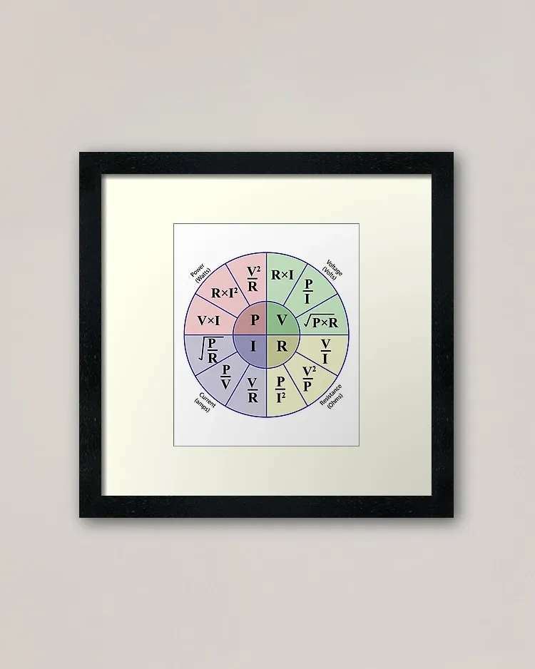
- The power wheel organizes four primary electrical variables: voltage (V), current (I), resistance (R), and power (P).
- Ohm’s Law specifically dictates the linear relationship between voltage, current, and resistance in a static system.
- PIR sensors require stable voltage and current levels to function, making these calculations vital for preventing sensor damage.
- Always verify your circuit’s total current draw against the power supply’s maximum output to avoid thermal failure.
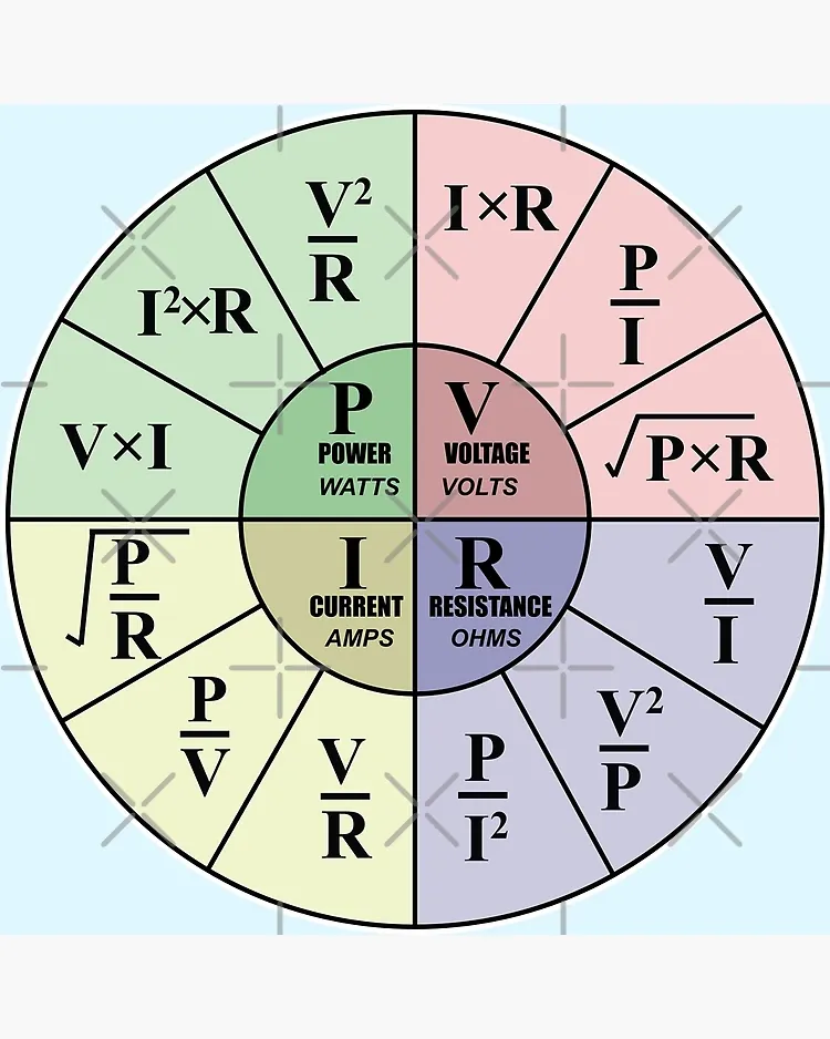
- Using a visual wheel allows you to solve for unknown variables instantly by covering the value you need to find.
What is the Power Wheel?
The power wheel is a diagnostic tool that combines Ohm’s Law and the Watt’s Law formulas into a single, comprehensive reference chart. While Ohm’s Law focuses on the relationship between voltage, current, and resistance, the power wheel incorporates power—measured in watts—to help you determine the energy consumption of your components. It’s split into four quadrants, with each quadrant providing the specific formulas required to calculate one of the four variables based on the other known values.
Understanding the Variables
- Voltage (V): The potential difference measured in volts, representing the “pressure” pushing electrons through the circuit.
- Current (I): The flow rate of electric charge measured in amperes, which determines how much energy is being moved.
- Resistance (R): The opposition to current flow measured in ohms, which dictates how much voltage is lost across a component.
- Power (P): The rate of energy transfer measured in watts, calculated by multiplying voltage by current.
How to Apply Ohm’s Law
Ohm’s Law is expressed as V = I × R. This simple equation tells you that the voltage across a conductor is directly proportional to the current flowing through it, provided the resistance remains constant. When working with a PIR (Passive Infrared) sensor, you often need to determine the value of a current-limiting resistor to prevent the sensor from drawing too much current from a microcontroller pin, such as those found on an Arduino or Raspberry Pi.
| Variable | Symbol | Unit of Measure | Relationship |
|---|---|---|---|
| Voltage | V | Volts (V) | V = I * R |
| Current | I | Amperes (A) | I = V / R |
| Resistance | R | Ohms (Ω) | R = V / I |
| Power | P | Watts (W) | P = V * I |
Integrating Sensors into Circuits
When you integrate a motion-detecting PIR sensor into your project, you must ensure the power supply is adequate. Most PIR modules operate between 3.3V and 5V. If your input voltage exceeds the sensor’s maximum rating, you’ll need a voltage divider circuit. This is where the ohm’s law and pir wheel methodology becomes practical; you calculate the resistance needed to drop the voltage to a safe level without starving the sensor of the necessary operating current.
Warning: Always double-check your polarity before applying power to a PIR sensor, as improper connections can cause immediate damage to the internal infrared detection circuitry.
Why Use the Wheel Method?
The wheel method is superior to memorizing individual formulas because it provides a visual representation of how variables interact. If you have a circuit where you know the voltage and the desired current, you can look at the wheel to instantly see that Resistance equals Voltage divided by Current. This prevents errors during the design phase of sensitive electronic projects.
Common Calculations
- Voltage Drop: Determining how much voltage is lost across a long wire run.
- Power Dissipation: Ensuring your resistors are rated for the heat they will generate.
- Current Limiting: Calculating the necessary resistance to protect LEDs or logic gates.
- Battery Life: Estimating how long a power source will last based on total system wattage.
Troubleshooting Common Circuit Issues
When a PIR sensor fails to trigger or behaves erratically, the issue is often related to power instability. Use your digital multimeter to measure the actual voltage at the sensor pins. If the reading is lower than the specified threshold, your total system current draw might be exceeding the capacity of your power supply.
Pro Tip: Use a bypass capacitor placed as close to the PIR sensor’s power pins as possible to smooth out voltage ripples and prevent false triggering caused by noise.
| Symptom | Potential Cause | Solution |
|---|---|---|
| Sensor not triggering | Low input voltage | Check power supply capacity |
| False triggers | Electrical noise/EMI | Add a small decoupling capacitor |
| Overheating components | Excessive current flow | Increase series resistance |
| Intermittent operation | Loose wiring/Resistance | Ensure all connections are secure |
Are These Formulas Always Accurate?
While these mathematical models are highly accurate for resistive loads, real-world components can introduce non-linear behaviors. For example, the resistance of an incandescent bulb changes as it heats up, meaning Ohm’s Law only applies to that component at a specific temperature. For standard digital sensors like those found in motion detectors, these laws remain the gold standard for circuit analysis.
Understanding PIR Sensor Requirements
PIR sensors detect infrared radiation changes. To operate effectively, they require a stable supply of current to maintain the internal op-amp and signal processing logic. The National Institute of Standards and Technology notes that precise electrical measurements are essential for the reliability of all sensor-based systems. By utilizing the power wheel, you ensure that your PIR sensor receives the exact current required for its detection range to remain consistent.
Can You Use the Wheel for AC?
The standard power wheel is primarily designed for DC (Direct Current) circuits. When working with AC (Alternating Current), you must account for impedance rather than just simple resistance. Impedance includes resistance along with reactance from capacitors and inductors, which changes based on the frequency of the power supply. For basic PIR projects that utilize DC power adapters, you can safely stick to the standard wheel.
Is Power Always Equal to V times I?
In DC circuits, yes, the formula P = V × I is universally applicable. In AC circuits, you must incorporate the power factor, which represents the efficiency of the electrical load. However, for the low-voltage electronics typically used with PIR sensors, the DC version of the power wheel is perfectly sufficient for your needs and will provide accurate results for your design requirements.
How to Calculate Ohm’s Law for PIR Wheel Loads
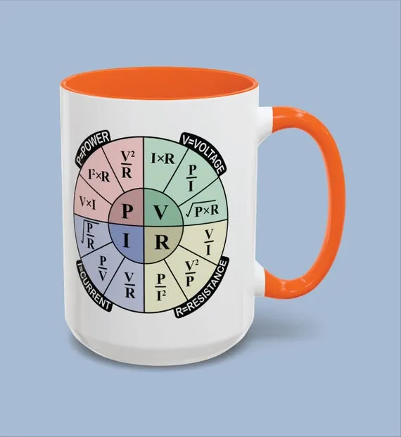
To calculate the total load of your project, list every active component, including the PIR sensor, LEDs, and microcontrollers. Find the current draw for each device in its datasheet. Sum these values to get the total current (I). Once you have the total current and your supply voltage (V), use the power wheel to find the total power (P) your supply must be capable of providing.
Frequently Asked Questions
Does wire length affect Ohm’s Law?
Yes, wire length introduces resistance. Every conductor has a specific resistance per foot, which causes a voltage drop over long distances. If your PIR sensor is located far from the power source, you must account for this additional resistance in your calculations to ensure the sensor receives the minimum required operating voltage.
What happens if I ignore the power ratings?
Ignoring power ratings usually leads to thermal failure. If a resistor is forced to dissipate more power in watts than it’s rated for, it will overheat, potentially burn out, or even catch fire. Always check the wattage rating of your resistors, which typically ranges from 0.125W to 0.5W for standard breadboard projects.
Can I use the wheel for high-voltage circuits?
The mathematical principles remain the same regardless of voltage, but the safety requirements change drastically. When working with high-voltage AC, the risk of arc flash and electric shock is significant. Only perform calculations for high-voltage circuits if you’re a qualified professional, and always ensure your equipment is properly insulated and rated for the voltage levels present.
How do I find unknown resistance?
To find unknown resistance, rearrange the Ohm’s Law formula to R = V / I. Measure the voltage across the component and the current flowing through it using a multimeter. Divide the voltage by the current to reveal the resistance in ohms. This is particularly useful for identifying the values of older, unmarked resistors or verifying that a component is functioning correctly.
Why does my PIR sensor act erratically?
Erratic behavior is often caused by voltage drops. If the PIR sensor’s voltage falls below its minimum threshold during a trigger event, the internal logic may reset or produce false signals. Use the power wheel to verify that your power supply provides enough current to handle the sensor’s peak demand during active detection cycles, and stabilize the input with a capacitor.
Conclusion
Start your next project by sketching your circuit diagram and labeling every known value of voltage, current, and resistance. Once you have identified the missing variable, apply the relevant formula from the power wheel to determine the exact component specifications you need. By following these methodical steps, you’ll build robust, reliable circuits that function perfectly every single time.
