
Thermal modelling uses computer software to simulate physical laws and track energy flow through virtual materials. By inputting geometry, heat sources, and material properties, the program solves complex equations to identify where heat builds up or escapes. This digital simulation of thermodynamics allows designers to test their work before construction.
How thermal modelling predicts heat

The accuracy of your simulation depends on the quality of the data you provide to the software. If you provide incorrect material properties, the output will be wrong regardless of the software’s power. You can check these values in the National Institute of Standards and Technology material properties database to ensure your inputs match physical reality.
| Part or input | What it does | What you notice when it goes wrong |
|---|---|---|
| Geometry model | Defines the shape and size | Heat flows through impossible gaps |
| Material properties | Sets how heat moves | Temperature changes too fast or slow |
| Boundary conditions | Defines the surrounding environment | Results ignore real-world cooling effects |
| Heat sources | Adds energy to the system | Predicted temperatures are too low |
| Mesh resolution | Breaks model into small pieces | Results look jagged or inaccurate |
Always verify your thermal conductivity values at the specific operating temperature of your system. Materials often behave non-linearly; using a room-temperature constant for a component running at 300 degrees Celsius will cause significant divergence. If the material is anisotropic, such as a carbon-fiber composite, you must define the conductivity tensor for each axis. Failing to account for directional heat flow leads to localized hotspots that physical testing will reveal immediately.
When defining boundary conditions, distinguish between forced and natural convection. If your component sits in stagnant air, use a heat transfer coefficient between 5 and 25 W/m²K. If a fan provides active cooling, that value can jump above 100. Choosing the wrong coefficient is the most common error in thermal modeling, often resulting in a 20 percent margin of error in your final temperature estimates.
Steps for running a thermal simulation
Following a consistent process helps you get reliable results every time you run a study. If you skip the validation step, you might trust a model that’s fundamentally flawed.
- Create a 3D digital model of the object you want to test, ensuring all parts are connected correctly. This step usually takes 10 to 60 minutes depending on complexity.
- Assign thermal conductivity, density, and specific heat values to every material in the model. You can find these values in the manufacturer’s technical documentation for each component.
- Apply the boundary conditions, such as ambient air temperature or fixed heat sinks. This assumes the environment is stable; for fluctuating conditions, you must use a transient simulation.
- Define your heat sources by specifying the power in watts. If you’re modeling electronics, check the component data sheet to find the exact thermal output at peak usage.
- Generate the mesh, which divides the object into thousands of small elements. A finer mesh improves accuracy, but it increases calculation time significantly for large or complex assemblies.
- Run the solver and wait for the software to calculate the temperature distribution. This can take anywhere from a few seconds to several hours based on the mesh size.
- Review the results to identify hotspots or areas where heat isn’t dissipating as expected. If the temperature exceeds your limits, you must adjust the design and re-run.
Why simulation accuracy affects design success
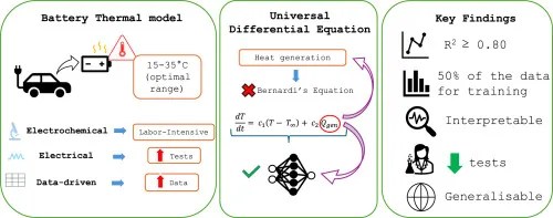
Thermal modelling translates abstract physics into visual maps that show exactly where a product might fail. A mistake people often make is assuming that adding more cooling surface area always lowers the temperature. If you add fins without considering airflow, you might accidentally create a heat trap that keeps the air stagnant.
This happens because heat moves through conduction, convection, and radiation. If your model fails to account for air movement, the simulated temperature will be much higher than what you see in the real world. You must decide if you need a steady-state analysis or a transient one. If your device heats up slowly over hours, use transient; if it reaches a constant temperature during continuous operation, use steady-state.
The trade-off is always between speed and precision. A very fine mesh gives you incredible detail but might take all night to finish. A coarse mesh is fast but can miss critical hotspots on small components. If you find your results change drastically when you make the mesh finer, your current results are likely unreliable. Always test with a coarser mesh first to confirm your inputs are logical.
Controls and design constraints
Things you can change
- Adjust the thickness of materials to improve heat conduction.
- Change the surface finish to increase heat radiation.
- Add or move heat sinks to pull energy away from sensitive parts.
- Modify the surrounding airflow to improve convective cooling.
Constraints fixed by design
- The inherent thermal conductivity of your chosen materials.
- The physical space available for cooling components.
- The laws of physics governing heat transfer rates.
If your design requires extreme cooling or handles high-voltage electricity, you must consult a professional thermal engineer. Making mistakes here can cause physical damage or fire hazards that basic software can’t prevent.
Habits for better thermal predictions

Effective thermal modelling requires a disciplined approach to how you interpret your data. Always start with a simplified model to ensure your boundary conditions are correct before adding complex details. If the simple model doesn’t behave as expected, the complex one will be even harder to debug.
Always perform a sensitivity analysis by changing one variable at a time. If you change the material, the heat source, and the geometry simultaneously, you’ll never know which change caused the shift in temperature. Keep a log of your assumptions, such as the assumed ambient air temperature. This allows you to recreate your results if you need to revisit the project after several weeks.
Compare your simulation results against a known physical test whenever possible. This gives you confidence that your software settings match reality. If you have no physical test data, look for similar published studies for your specific materials. This validation step is the only way to ensure your predictions are grounded in fact rather than just software output.
Related guides
- Best Heat Tape Pipe Heating Cables: How to Prevent Frozen Pipes in 2026
- The Best Way to Fill Your Hot Tub in Winter: Heated Hose Fix in 2026
Frequently asked questions
Can thermal modelling predict heat for any material?
Thermal modelling can predict heat for any material as long as you have the correct thermal conductivity and specific heat capacity values. You can find these constants in the documentation provided by your material supplier. If the material properties change with temperature, you must input a range of values for accuracy.
Why do my simulation results differ from real-world tests?
Differences usually occur because your boundary conditions don’t match the real environment or your material inputs are inaccurate. Check if you have properly accounted for air movement, as even small fans change the outcome. Ensure your software settings for contact resistance between parts are realistic for your specific assembly method.
How long does a thermal simulation take to run?
The time depends on the number of elements in your mesh and your computer’s processing power. Simple models can finish in under 1 minute, while complex assemblies can take several hours. If your model takes too long, try reducing the mesh density in areas that aren’t critical to your thermal analysis.
Is it safe to rely on thermal modelling for safety-critical parts?
It’s safe to use as a design tool, but you must validate the results with physical testing before finalizing any safety-critical product. The simulation is only as good as the data you provide. Never use software results as a substitute for certified testing required by law or industry safety standards.
What happens if I use the wrong material properties?
Using the wrong values leads to incorrect temperature predictions that can cause your physical product to overheat and fail. If the conductivity is too high in your model, the heat will appear to spread faster than it actually does. Always verify material data against official manufacturer tables to avoid these major design errors.
How many heat sources can I include in one model?
You can include as many heat sources as your software’s capacity allows, but each one adds complexity to the calculation. If you have dozens of small heat sources, group them into a single thermal load if they’re close together. This simplifies the simulation while maintaining enough accuracy for most design purposes.
Conclusion
By simulating these invisible forces, you’ll avoid costly mistakes and refine your ideas with confidence. Don’t wait until the prototype stage to find flaws; start running your first simulation today. You’ll be surprised at how much clearer your design process becomes once you can actually see the heat moving through your work.
