
Selecting the right logic for industrial automation requires a deep understanding of how different coding styles impact machine performance and maintenance, which is why professionals frequently consult a plc programming languages a comparative guide to ensure their system architecture aligns with project requirements. Programmable Logic Controllers serve as the backbone of modern manufacturing, and the industry standard for these devices is governed by the IEC 61131-3 international specification. Understanding these languages allows engineers to balance visual clarity with mathematical precision, ensuring that complex sequences remain both functional and debuggable over the long term.
Key Takeaways
- Ladder Diagram (LD) is the industry standard for maintenance teams due to its visual resemblance to electrical relay logic.
- Structured Text (ST) offers high-level programming capabilities, making it the superior choice for complex mathematical algorithms and data manipulation.
- Function Block Diagram (FBD) excels in process control applications where repetitive loops and signal processing are required.
- Sequential Function Chart (SFC) provides a structured, top-down approach to managing state-based machine sequences.
- Instruction List (IL) is a low-level, assembler-style language that’s increasingly deprecated in favor of more readable alternatives.
What Are the Standard Languages?
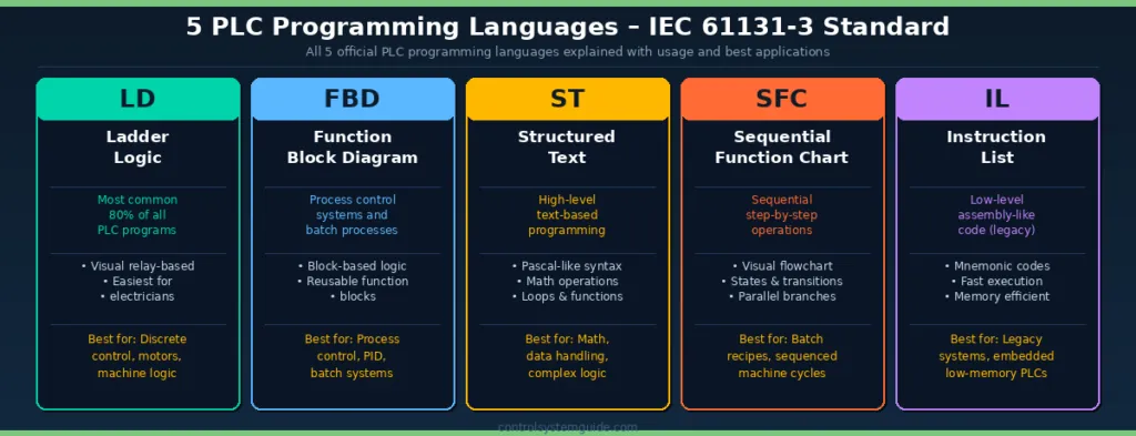
The IEC 61131-3 standard defines five distinct languages that manufacturers must support to ensure interoperability across different platforms. These languages were developed to cater to different engineering backgrounds, ranging from electrical technicians to software developers. Each language has specific use cases that make it more or less suitable for a given automation task.
| Language | Primary Focus | Best For |
|---|---|---|
| Ladder Diagram | Relay Logic | Simple boolean control |
| Structured Text | High-level Syntax | Complex math/arrays |
| Function Block | Data Flow | Process control loops |
| Sequential Function | State Machines | Step-based sequences |
| Instruction List | Low-level CPU | Optimized execution speed |
Which Language Suits Your Needs?
Choosing the right language often depends on the specific hardware brand, such as Siemens, Allen-Bradley, or Beckhoff, and the skill set of the personnel who will troubleshoot the machine. For instance, Ladder Diagram is often mandated in automotive plants because maintenance technicians are highly trained in reading relay logic. Conversely, data-heavy applications involving PID loops or protocol communication typically favor Structured Text or Function Block Diagram.
Ladder Diagram for Maintenance Efficiency
Ladder Diagram remains the most widely used language in the world because it mimics physical electrical schematics. This visual representation allows a technician to look at a screen and see exactly which contact is open or closed, which is invaluable during downtime.
Pro Tip: Use Ladder Diagram for simple interlocks and safety circuits, but avoid using it for complex calculations, as the logic can become difficult to follow once the rungs extend beyond a single page.
Common Ladder Diagram elements:
- Normally Open (NO) contacts.
- Normally Closed (NC) contacts.
- Output coils.
- Timers and counters.
Structured Text for Complex Logic
Structured Text is a text-based language that looks similar to C or Pascal. It’s incredibly powerful for handling large data sets, performing intricate calculations, and managing communication protocols. Because it’s compact, it allows developers to write extensive logic in a small amount of space. This density is a double-edged sword; it’s efficient but requires a higher level of programming expertise to read and debug effectively compared to graphical languages.
Function Block Diagram Capabilities
Function Block Diagram is excellent for visual programmers who prefer a block-based approach. You connect blocks representing functions—like PID controllers or filters—with lines representing data flow. This makes it ideal for continuous process control where signal processing is the primary goal. The International Electrotechnical Commission maintains the formal standards for these programming environments to ensure global consistency in industrial software development.
Sequential Function Chart Advantages
Sequential Function Chart isn’t a standalone language in the traditional sense, but rather a way to organize the execution of other languages. It breaks a machine process into distinct steps and transitions. This is perfect for systems that must follow a specific sequence, such as a pick-and-place robot or a batching system.
Warning: Avoid nesting too many sub-routines within a single SFC transition, as this can make the flow of the program opaque and difficult to trace during a machine crash.
Instruction List and Its Decline
Instruction List is essentially assembly language for PLCs. While it’s technically the fastest language for a processor to execute, it has fallen out of favor in most modern industrial applications. Because it lacks the readability of graphical languages and the structure of high-level text languages, it’s prone to human error and is rarely used for new projects today.
Troubleshooting Your PLC Logic
Effective troubleshooting begins with choosing the right language for the task at hand. If you have a machine that’s constantly failing, the problem may be the language itself. For example, trying to perform complex matrix math in Ladder Diagram will result in hundreds of rungs of code that are nearly impossible to audit. Switching to Structured Text for that specific module can reduce your code base by 80% and make the logic transparent.
Common troubleshooting steps:
- Verify the scan cycle time of your controller.
- Monitor online status using the vendor software.
- Check for memory overflow errors in high-level modules.
- Validate input signal integrity before debugging code.
Integrating Multiple Languages
Most modern PLC platforms allow you to mix and match these languages within a single project. You can have a main routine in Sequential Function Chart that calls a PID block written in Function Block Diagram, which then references a data array processed by a Structured Text function. This modular approach is the mark of a sophisticated control system. It allows you to use the right tool for every part of your machine, ensuring both performance and maintainability.
Best Practices for Programming
Regardless of the language chosen, documentation is paramount. Always include descriptive comments in your code. Use clear, consistent naming conventions for your tags and variables. A well-organized program with clear variable naming is easier to support than a poorly named program, even if the latter is written in a more “advanced” language. Stick to a standard style guide to ensure that anyone who inherits your project can understand your logic structure immediately.
Related guides
- 8 Best Smart House System Picks for Seamless Home Automation in 2026
- 6 Best Pool Automation Systems for Easy Equipment Management in 2026
- 10 Best Z Wave Smart Plug Options for Reliable Home Automation in 2026
Frequently Asked Questions
Is Ladder Diagram still relevant?
Yes, Ladder Diagram is the most widely used language globally. Its primary strength lies in its similarity to electrical relay logic, which makes it the standard choice for maintenance teams who need to troubleshoot hardware issues quickly without needing a deep background in computer science or complex software engineering.
Can I learn all five languages?
While you can learn all five, most engineers specialize in two or three. Ladder Diagram and Structured Text are the most essential for modern industry. Mastering these two will cover approximately 90% of all industrial control applications. The others are niche tools that are helpful to know but aren’t strictly required for most entry-level or mid-level automation roles.
Which language is best for beginners?
Ladder Diagram is the best starting point for beginners. Its visual nature provides an immediate, intuitive understanding of how logic flows from inputs to outputs. Once you’re comfortable with boolean logic and basic timers, transitioning to Structured Text is a logical next step to handle more advanced tasks like data arrays and complex mathematical operations.
Do I need to be a programmer?
You don’t need to be a professional software developer to work with PLCs, but you must have a logical mindset. While some languages like Structured Text require traditional coding skills, others like Ladder Diagram are designed specifically for people with backgrounds in electrical systems and hardware maintenance rather than pure computer science.
How do I choose between languages?
Choose based on the task: use Ladder for simple interlocks, Function Block for control loops, and Structured Text for data manipulation. If your machine operates in discrete steps, use Sequential Function Chart to organize the workflow. Always consider the skill level of the maintenance team, as the best code is code that someone else can actually fix when the machine goes down.
Why is Instruction List fading?
Instruction List is difficult to read and maintain. It lacks the structure and visual feedback that modern, safety-critical industrial applications require. As processor speeds have increased significantly, the marginal performance gains of using assembly-style code no longer justify the massive loss in human readability and the increased risk of programming errors during the development and maintenance phases.
Conclusion
By carefully selecting the language that best fits your specific automation challenge, you’ll significantly reduce development time and future maintenance headaches. Start by mapping your process requirements to the strengths listed in this guide. Once your logic is structured, dedicate time to testing each module independently to ensure reliability before full system integration.
