
A digital logic circuit is a system that processes binary information using electrical signals to perform calculations or control operations. It works by taking input voltages representing 0s and 1s, passing them through gates to follow specific Boolean rules, and producing an output signal. Think of it like a smart light switch that only turns on when two other switches are flipped at the exact same time.
Essential logic circuit components
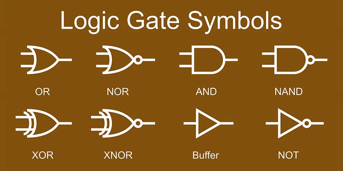
These parts are the building blocks that allow a system to handle complex data. You can check the specific part number on the component label or your device’s schematic to confirm its function.
| Part or input | What it does | What you notice when it goes wrong |
|---|---|---|
| Logic Gate | Compares signals to produce result | Incorrect output for given inputs |
| Power Supply | Provides stable voltage for gates | System resets or erratic behavior |
| Input Pin | Receives external binary voltage | Signal is ignored or always high |
| Clock Signal | Synchronizes all system operations | Data errors or timing failures |
| Output Pin | Sends result to next stage | No signal reaches next part |
If your system resets during high-load tasks, have a technician test the power supply rail. A drop below the nominal rating often triggers these failures.
Distinguish between a logic failure and a timing issue by checking the clock signal with an oscilloscope. If the waveform is rounded rather than square, the clock is failing to switch states fast enough for the logic gates.
Many engineers mistake a floating input pin for a high signal. Always use a pull-up or pull-down resistor to ensure the pin stays at a known state. Without this, ambient electrical noise will cause the system to trigger randomly, costing you hours of troubleshooting time.
How signals move through gates
The process follows a set path from raw input to the final result. Each step happens in a fraction of a second, usually measured in nanoseconds depending on the chip’s technology.
- The input voltage arrives at the pins, where a high voltage represents a binary 1 and a low voltage represents a 0.
- The signal enters the first logic gate, which evaluates the binary state against its specific rule, such as an AND or OR function.
- The gate processes the data in approximately 1 to 10 nanoseconds, assuming a standard CMOS gate design; older hardware or larger components may be slower.
- The output of this gate acts as the input for the next stage, creating a cascade effect through the entire system.
- The combined signals reach the final output buffer, which stabilizes the voltage for the connected device or display.
- The entire cycle repeats as long as the clock signal continues to pulse at the designated frequency for that specific processor.
Why signal path errors matter
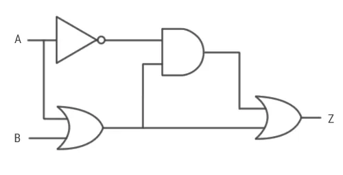
The reliability of any electronic device depends on the integrity of its binary signal path. When a component fails, the entire chain breaks because the output of one gate serves as the necessary input for the next. If a gate receives a weak or “floating” signal, it can’t decide whether to output a 1 or a 0, leading to random errors.
Temperature fluctuations often cause these issues. Extreme heat can change the resistance of internal pathways, causing signals to arrive too late for the system clock. According to technical guidance from the IEEE, timing margins are critical for preventing data corruption in complex integrated systems. If you notice your device crashing only after it warms up, the issue is likely a physical degradation of the board or a failing power component.
Another common mistake is ignoring power quality. Many people assume a power supply is either working or dead, but a supply that provides “noisy” voltage creates ripple effects. This noise looks like a logic signal to sensitive gates, causing them to switch states when they should remain idle. If the power source fluctuates outside the manufacturer’s specified tolerance, the logic becomes unpredictable.
Control and design limits
You can manage the environment and external connections, but the internal architecture is fixed once the silicon is printed.
What you control
- The input voltage range applied to the external pins.
- The operating temperature of the surrounding device environment.
- The frequency of the clock signal in programmable hardware.
- The cleanliness of the board to prevent short circuits.
What is fixed
- The internal threshold voltages for logic states.
- The physical arrangement of the gates on the chip.
- The maximum switching speed of the transistors.
If your project requires changing these physical limits, you need specialized hardware design software and high-precision soldering tools. Most tasks involving the repair of internal chip logic require professional equipment, as a single mistake can permanently destroy the circuit board.
Habits for reliable performance
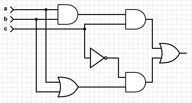
Maintaining a digital system requires consistent care to prevent signal degradation. First, always keep the device within the temperature range listed in the manufacturer’s manual. High heat increases electrical resistance, which slows down the signal and causes timing errors.
Second, use a stable power source. Voltage spikes or drops can force gates to switch incorrectly, leading to data loss that’s difficult to trace. If you operate in an area with frequent outages, a dedicated uninterruptible power supply is recommended to prevent data loss and system crashes.
Third, keep the area around the board free of dust and moisture. Conductive debris can create tiny bridges between pins, turning a 0 into a 1 and confusing the logic. If you see visible accumulation, use canned air held at a six-inch distance to clear the path.
Finally, avoid touching the board with your bare hands. The oils from your skin are slightly acidic and can corrode thin metal traces. If you suspect a connection is failing, use a non-conductive contact cleaner specifically designed for electronics to remove buildup safely.
Related guides
- How an Optical Signal Transmits Information: A Simple Guide
- What Is Quenching the Process and Its Purpose Explained
- How the Laser Brazing Process Works: A Step-by-Step Guide
Frequently asked questions
How fast does a logic gate switch?
A standard gate switches in about 1 to 10 nanoseconds, but this speed varies based on the manufacturing process used for the chip. You can find the exact propagation delay for your specific component by checking the datasheet provided by the manufacturer.
Is it safe to touch a logic circuit?
It’s generally safe to touch the board if the power is off, but you risk damaging the parts with static electricity. Always use an anti-static wrist strap to ground yourself before you touch the components to prevent a discharge that could destroy the sensitive gates.
Why does my circuit get errors when it gets hot?
The error occurs because heat changes the electrical resistance of the materials, which slows down the signal timing. The gates then fail to sync with the clock signal, causing the system to process data incorrectly or crash entirely.
How do I know if a gate is broken?
You can identify a broken gate by measuring the output voltage with a multimeter while the input is known. If the output doesn’t match the expected binary result defined in the truth table for that specific gate, the internal hardware is likely damaged.
Can a logic circuit work without a clock?
A circuit can work without a clock if it’s an asynchronous design, but most modern systems rely on a clock to stay synchronized. If you’re using a synchronous chip, it won’t function or will produce garbage data without a steady clock signal.
What happens if the voltage is too low?
The logic will fail to distinguish between a 0 and a 1, causing the system to behave randomly. Each chip has a minimum operating voltage listed on its official spec sheet, and dropping below this threshold prevents the transistors from switching properly.
Does the order of the gates matter?
The order is critical because each gate depends on the output of the previous one to calculate the final result. If you rearrange the gates or the signal path, you change the Boolean logic of the entire system and produce a different output.
Conclusion
Once you’re comfortable with basic gates, grab a breadboard and a few LEDs to build something real. You don’t need expensive tools—just curiosity and a steady hand. Tinkering with physical wires is where the theory finally clicks, and it’ll make your next project feel much less intimidating.
