
You calculate the friction factor for pipe flow by first finding the Reynolds number and then applying the Colebrook-White equation to account for pipe roughness. This process determines how much energy your fluid loses as it travels through a system. It works best for engineers or students dealing with steady-state flow in closed conduits who need accurate pressure drop predictions.
Required tools for fluid calculations
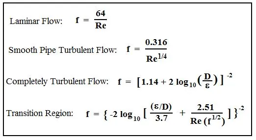
You must gather specific data to ensure your results match the physical reality of your piping system. Without these inputs, your calculated values won’t represent the true behavior of the fluid.
- Fluid velocity (v): The average speed of the fluid in meters per second.
- Pipe diameter (D): The internal diameter of the pipe in meters.
- Kinematic viscosity (ν): The thickness of the fluid, which changes based on temperature.
- Pipe roughness (ε): The average height of surface irregularities inside the pipe wall.
- Scientific calculator: A device capable of handling logarithmic functions and iterative solving.
- Moody diagram: A graphical reference used to verify your numerical results.
If you lack the exact roughness value for your material, you can use standard values published by The Engineering Toolbox for common materials like steel or PVC. Never guess these numbers, as a small error in roughness estimation leads to large discrepancies in predicted pressure loss. If your project involves high-pressure lines, consult a licensed professional engineer to verify your safety factors.
Steps to determine pipe friction factor
- Calculate the Reynolds number by multiplying the fluid velocity by the pipe diameter, then dividing that result by the kinematic viscosity. If the Reynolds number is below 2,300, the flow is laminar, and the friction factor is simply 64 divided by the Reynolds number.
- Identify the pipe roughness value (ε) based on the material of your pipe, such as drawn tubing or galvanized iron.
- Determine the relative roughness by dividing the pipe roughness (ε) by the internal pipe diameter (D).
- Use the Colebrook-White equation to solve for the friction factor (f) when the flow is turbulent, which occurs at a Reynolds number above 4,000.
- Apply an iterative method because the friction factor appears on both sides of the equation, requiring you to guess an initial value and refine it until the result stabilizes.
- Check your result against the Moody diagram to ensure the calculated friction factor falls within the expected range for your specific Reynolds number and relative roughness.
Tip: For turbulent flow, you can use the Haaland equation as a simpler, non-iterative approximation that provides results within 2% of the more complex Colebrook-White method.
Careful: Always ensure your units are consistent; mixing inches with meters will result in a completely incorrect Reynolds number and render your final friction factor useless.
Adjusting for different flow conditions
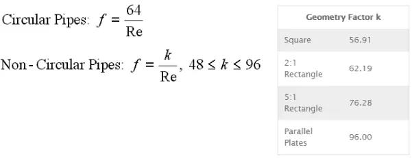
The difficulty of the calculation depends on the state of the fluid and the pipe’s internal condition. You should adjust your approach based on the specific environment of your system.
| Situation | Effort Level | Key Difference | Watch For |
|---|---|---|---|
| Laminar flow | Low | Simple division | Temperature changes |
| Smooth pipe | Medium | Negligible roughness | Fluid density |
| Rough pipe | High | Iterative solving | Scale buildup |
| Turbulent flow | High | Complex equations | Velocity fluctuations |
It’s safer to start with a conservative estimate of pipe roughness and refine your numbers as you gather more field data, rather than assuming a perfect surface on the first try.
Validating your calculated results
A correct friction factor result typically sits between 0.01 and 0.05 for most common industrial pipe flows. If your result is significantly higher or lower, you likely made a unit conversion error or misidentified the flow regime as turbulent when it was actually laminar. This problem often stems from using the wrong viscosity value for the fluid at the operating temperature.
To prevent these errors, always verify the fluid temperature first, as viscosity changes drastically even with small shifts in heat. You should also re-check your diameter units, as standard pipe sizes often differ slightly from their nominal descriptions. If you notice your calculated pressure drop doesn’t match your physical gauge readings, check for partial blockages or valve restrictions that increase the effective roughness beyond the pipe’s base material value.
Standards and post-calculation tasks
The standard for these calculations is maintained by the American Society of Mechanical Engineers (ASME), which provides guidelines for fluid transport systems. Once you finish, record your final friction factor and the temperature of the fluid in your project logbook.
If you’re designing for a critical system, have your calculations audited by a professional. A common mistake is assuming a static roughness coefficient for the life of the project. This oversight often leads to a 10% drop in flow efficiency within the first year of operation.
Recalculate the friction factor based on your specific usage patterns and monitor the system for signs of degradation. When in doubt, assume a 15% margin of error for long-term degradation.
Alternative methods for friction analysis

Using the Moody diagram
This graphical approach allows you to find the friction factor by plotting your Reynolds number and relative roughness on a pre-printed chart. It’s faster than manual iteration but less precise for final engineering reports. Use this method for quick field checks or to verify the magnitude of your numerical calculations.
Relying on software solvers
Many engineering software packages, such as Pipe-Flo or HYSYS, calculate friction factors automatically using built-in algorithms. This reduces human error but requires you to understand the underlying math to spot when the software receives bad input data. Use these tools only when you have verified the input parameters against your physical system.
Applying the Swamee-Jain equation
The Swamee-Jain equation provides a direct, explicit solution for the friction factor that doesn’t require iteration. It’s highly accurate for most common pipe flow scenarios and is suitable for spreadsheets. Use this when you need to calculate friction factors for many different pipe segments quickly without the need for complex solver tools.
Related guides
Frequently asked questions
Can I calculate the friction factor without knowing the pipe material?
No, you can’t accurately find the friction factor without the pipe roughness, which is determined by the material. If you don’t know the material, you must inspect the pipe or check the original construction blueprints to identify the interior surface condition, as this directly dictates the friction resistance.
How long does it take to calculate the friction factor?
It takes about 10 to 15 minutes for a single pipe section when using a calculator and the Haaland approximation. If you have a complex network with many branches and varying diameters, this process can take several hours, especially if you need to account for minor losses from valves and fittings.
Is it safe to ignore the friction factor in small pipes?
No, it isn’t safe to ignore friction, as energy loss is often higher in smaller pipes due to the increased surface-area-to-volume ratio. Even in small systems, the friction factor is necessary to ensure your pump has enough head pressure to deliver the required flow rate to the end of the line.
What happens if I use the wrong friction factor?
Using the wrong friction factor leads to an incorrect pressure drop prediction, which can cause your pump to either underperform or fail due to excessive resistance. An overestimated friction factor results in an oversized, expensive pump, while an underestimated factor leads to a system that fails to meet your flow requirements.
How often should I update my friction factor calculations?
Update your calculations whenever you change the fluid type, operating temperature, or perform maintenance on the piping system. If your system handles fluids that cause mineral buildup or corrosion, recalculate the friction factor regularly to account for increasing pipe wall roughness.
Conclusion
Once you’ve got your energy loss sorted out, you’re ready to size your pumps and pick the right pipe material. Don’t stop here—plug your numbers into a system model and see how changes in flow rate affect your overall design. You’ll save yourself plenty of headaches later.
