
Connecting to an Allen-Bradley PLC requires establishing a physical link between your computer and the controller, then using Rockwell Automation software to bridge that gap. This process involves configuring your network interface card or serial adapter, identifying the processor’s communication protocol, and using the RSLinx communication driver to establish a stable pathway for programming, monitoring, or troubleshooting your industrial automation hardware.
Key Takeaways
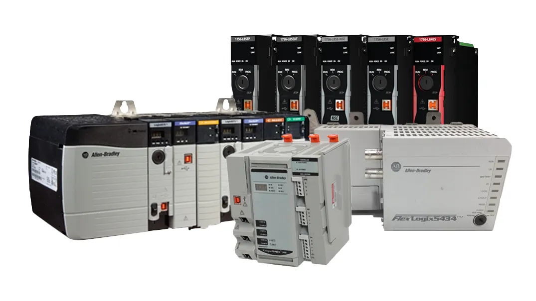
- Always verify your communication cable matches the specific PLC port type.
- Ensure your computer’s IP address is within the same subnet as the PLC.
- Use RSLinx Classic to manage communication drivers and browse network nodes.
- Disable local firewalls if you encounter issues detecting devices on Ethernet.
- Match your software version to the firmware version of the controller.
How to Connect to a PLC
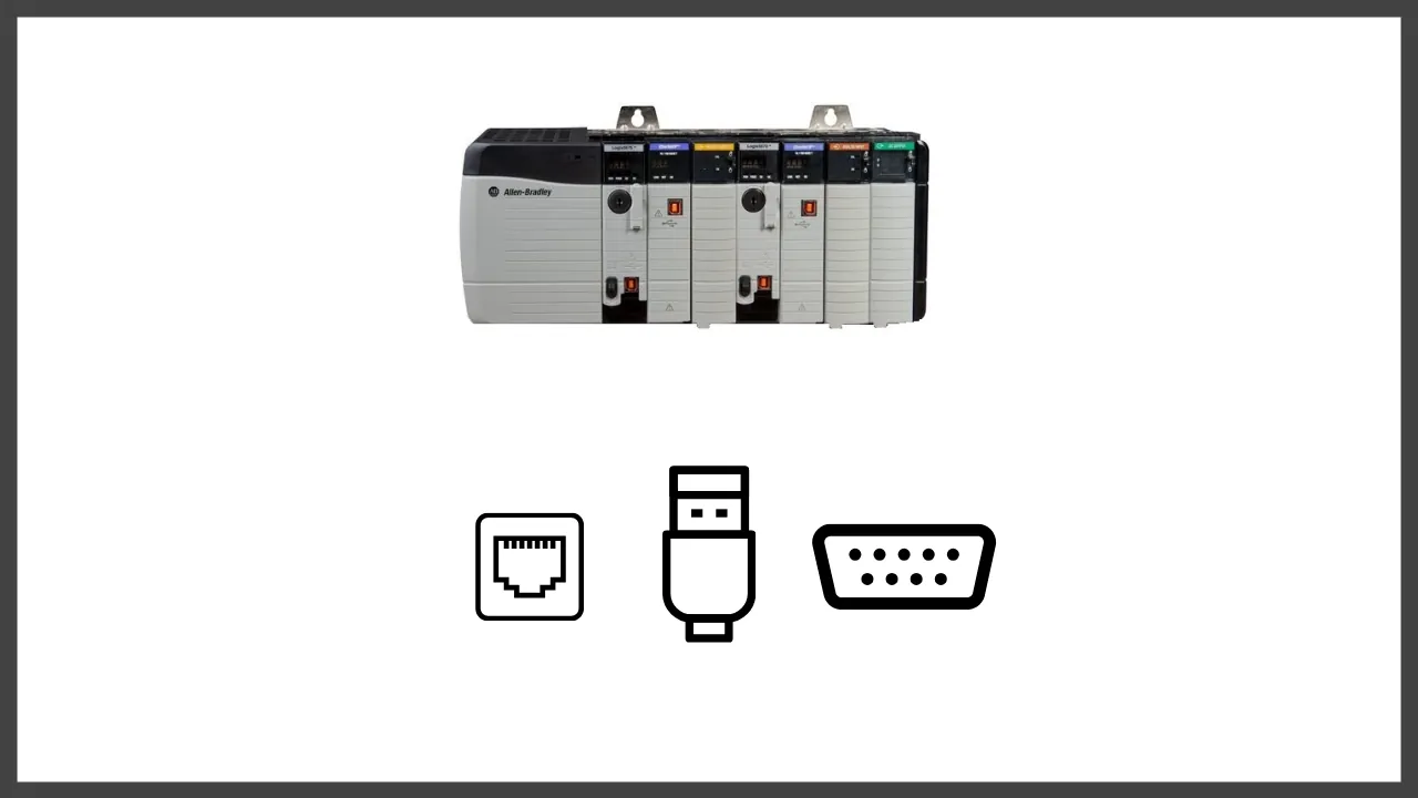
To begin, you must identify the physical port on your Allen-Bradley controller. Modern CompactLogix and ControlLogix processors typically utilize Ethernet/IP, while older SLC 500 or MicroLogix units may rely on RS-232 serial or DH+ connections. For Ethernet, connect a standard Cat6 patch cable from your PC’s network port to the PLC’s communication port or an upstream network switch. If using a serial connection, you’ll need a 1747-CP3 or similar null-modem cable and potentially a USB-to-Serial converter.
Pro Tip: If you’re using a USB-to-Serial adapter, verify the assigned COM port number in your Windows Device Manager, as Rockwell software often defaults to COM1, which rarely matches modern virtualized hardware.
Configuring Your Network Settings
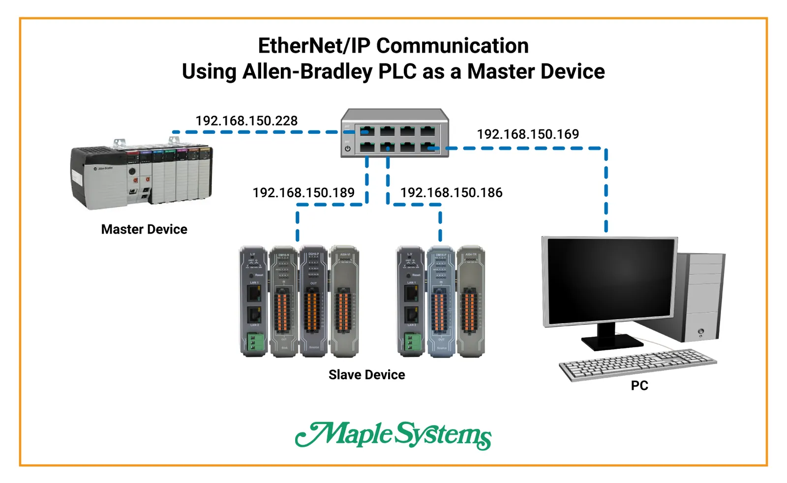
Your computer must exist on the same network segment as the PLC to initiate a handshake. If the PLC is set to a static IP address, such as 192.168.1.10, your computer must be set to an address like 192.168.1.5 with a matching subnet mask, typically 255.255.255.0. You can change these settings in your Windows “Network and Sharing Center” under the IPv4 properties of your Ethernet adapter.
| Connection Type | Typical Hardware Needed | Primary Protocol |
|---|---|---|
| Ethernet | Cat6 Cable / Switch | EtherNet/IP |
| Serial | 1747-CP3 Cable | DF1 Protocol |
| USB | 1784-U2DHP / USB Cable | DH+/CIP |
Using RSLinx to Connect to Allen Bradley PLCs
RSLinx Classic serves as the essential communication server that acts as a translator between your programming software (Studio 5000 or RSLogix) and the physical PLC. Open RSLinx and navigate to the “Communications” menu, then select “Configure Drivers.” For Ethernet, select “EtherNet/IP Driver” or “Ethernet Devices” depending on whether you’re browsing or manually entering an IP address. Once the driver is running, open the “RSWho” window to see if your PLC appears as a node.
Why is My PLC Not Appearing?
If the device doesn’t show up in the RSWho window, the most common culprit is a mismatch in network settings or a blocked port. Ensure that your PC’s firewall isn’t blocking the traffic; Rockwell software uses specific ports for discovery. Additionally, check that your Ethernet cable is plugged into the correct port on the PLC, as some processors have dedicated ports for local programming versus plant-wide network integration.
Matching Firmware and Software Versions
Allen-Bradley hardware is strictly version-dependent. If your PLC firmware is version 32, you must use Studio 5000 Logix Designer version 32 or higher to communicate effectively. Attempting to connect with an incompatible software version will often result in the controller being visible in RSLinx but unreachable for project uploads or downloads. Always check the Rockwell Automation Product Compatibility and Download Center to confirm that your specific controller firmware is supported by the version of the software installed on your workstation.
Essential Hardware and Software Requirements
To succeed, you need the appropriate tools to bridge the digital gap between the office environment and the factory floor. The following table details the necessary components for standard setups.
| Component | Purpose | Requirement |
|---|---|---|
| Programming Cable | Physical bridge | Must match port |
| RSLinx Software | Communication driver | Essential for all |
| Studio 5000 | Project environment | Logix 5000 series |
| RSLogix 500 | Legacy environment | SLC 500 / MicroLogix |
How to Troubleshoot Connection Failures
When communication remains elusive, perform a systematic check of your physical layer first. Inspect the link lights on both the PLC port and your computer’s network interface. If the lights are dark, the cable may be faulty or the port may be disabled. Next, use the Windows command prompt to “ping” the PLC’s IP address. If the ping fails, the issue is strictly network-related, such as a subnet mismatch or a bad static IP configuration.
Managing Serial Communication Settings
For older hardware using the DF1 protocol, the baud rate, parity, and stop bits must match exactly between the PLC and the RSLinx driver. The standard default for most Allen-Bradley serial ports is 19,200 baud, 8 data bits, no parity, and 1 stop bit. If these settings are misconfigured, you’ll receive a “Communication Timeout” error in RSLinx, indicating that the handshake process is failing due to data corruption or timing mismatches.
Warning: Never attempt to force a firmware update over a serial connection, as a communication dropout during the flash process can permanently “brick” the processor, requiring a factory repair.
Using Managed Network Switches
If you’re connecting through a managed switch, ensure that the ports aren’t configured for “Port Security” or “MAC Filtering.” These features can block unrecognized devices, including your laptop. If the PLC is on a different VLAN than your workstation, you’ll need to configure a gateway or use a specialized routing driver in RSLinx to allow the packets to pass between the subnets.
Verifying Cable Pinouts
Not all cables are created equal. A standard Ethernet patch cable is sufficient for Ethernet/IP, but serial connections require specific “null-modem” wiring. The 1747-CP3 cable is the industry standard for RS-232 communication with older Logix controllers. Using a generic serial cable that doesn’t match the pinout of the PLC port can result in an inability to establish a connection, even if the drivers appear to be configured correctly.
Related guides
Frequently Asked Questions
Can I connect via Wi-Fi?
Yes, you can connect via Wi-Fi if your PLC is on the same network as your wireless access point. However, Wi-Fi is generally discouraged for industrial environments due to signal instability and latency. For reliable programming and online monitoring, a hardwired Ethernet connection is the industry standard to prevent accidental disconnections during critical operations or firmware updates.
What if I forgot the IP address?
If the IP address is unknown, you can often use the “BOOTP/DHCP Server” utility provided by Rockwell Automation to identify the device. By connecting the PLC directly to your computer via Ethernet and power cycling the controller, the device will broadcast a request for an IP address, displaying its MAC address in the BOOTP utility, which allows you to assign a temporary static IP.
Does RSLinx require a license?
RSLinx Classic Lite is included with most Rockwell software packages and provides the basic functionality required to communicate with Allen-Bradley PLCs for programming and troubleshooting. You only need a paid license for RSLinx if you require advanced features like DDE/OPC communication, which allows data to be shared with third-party software like Microsoft Excel or other HMI visualization platforms.
How do I clear a communication error?
Most communication errors are cleared by restarting the RSLinx service. You can do this by opening the RSLinx application, selecting “File,” and choosing “Shutdown.” Once closed, reopen the application. If the error persists, check your Windows firewall settings to ensure that the RSLinx service is permitted to communicate across the network, or try power cycling the PLC itself to reset its communication module.
Can I use a USB to Ethernet adapter?
Yes, using a USB-to-Ethernet adapter is a common and effective way to connect to a PLC if your modern laptop lacks a native RJ45 port. Ensure that you have the latest drivers installed for your specific adapter and that your Windows network settings are correctly bridged to the virtual adapter. This provides a stable, high-speed connection that performs identically to a built-in Ethernet port.
Conclusion
Once you have successfully established a connection using RSLinx, the next logical step is to perform an “Upload” of the existing project file from the controller to your computer. This creates a backup of the current logic, ensuring you have a safe starting point before you make any modifications to the program or the hardware configuration in your production environment.
