
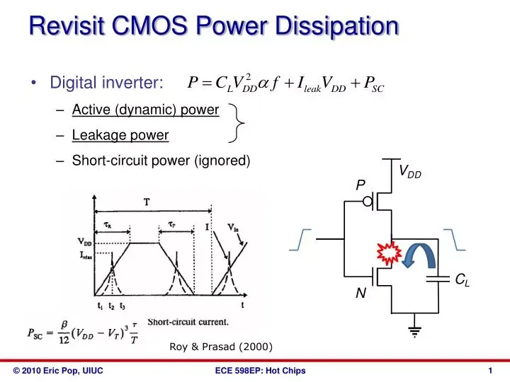
The dynamic power formula for chips is calculated as P = αCV²f, where P is power, α is the switching activity factor, C is the load capacitance, V is the supply voltage, and f is the clock frequency. This equation represents the energy lost during signal transitions within CMOS circuits. By adjusting these variables, engineers manage heat dissipation and energy consumption in modern electronic devices.
Efficiency in circuit design depends on how these variables interact during operation. The most critical factor is voltage, as it has a squared relationship with power consumption. If you double the frequency, power doubles, but if you double the voltage, power quadruples. A common mistake is ignoring the activity factor, which represents how often gates switch; assuming every gate switches constantly leads to massive overestimates of total power draw.
How to calculate dynamic power for chips
To estimate power, you must identify each variable for your specific hardware state. If you’re working with high-performance processors, the activity factor is often lower than you think. For low-power microcontrollers, reducing voltage is the most effective way to save energy.
-
Determine the load capacitance (C) for your specific circuit design in farads. This value is usually provided in the datasheet for your integrated circuit.
-
Identify the clock frequency (f) in hertz. This is the speed at which your processor or logic gate operates.
-
Measure the supply voltage (V) in volts. You can find this by checking the power rail input on your circuit board using a multimeter.
-
Estimate the switching activity factor (α), which is a decimal between 0 and 1. This represents the percentage of clock cycles where a gate output changes state.
-
Multiply these four values together to find the dynamic power in watts.
If you’re unsure of the activity factor, assume 0.1 for standard logic or 0.5 for high-toggle buses. A common mistake is using the theoretical supply voltage instead of the actual rail voltage. This oversight often leads to a 10% error in your final power budget.
Always verify the voltage at the chip pin rather than the power supply output, as line drops can change the actual value. If your chip has multiple voltage domains, perform this calculation separately for each domain and sum the results for total power. If you find your result exceeds the thermal design power, you must lower the frequency before attempting to adjust the capacitance.
Factors affecting chip power duration
The time it takes to reach a power limit depends on your cooling solution and the thermal design power of the component. Manufacturers define these limits for stable operation, but real-world duration depends on the thermal headroom available after the initial burst.
| Situation | Power Draw | What changes it | What to watch for |
|---|---|---|---|
| Idle state | Very low | Reduced frequency | Stability of clock gates |
| Light load | Moderate | Reduced activity factor | Efficient power gating |
| Heavy load | Peak | High voltage/frequency | Thermal throttling triggers |
| Turbo boost | Maximum | Increased voltage | Cooling capacity limits |
Identifying when power limits are met
You can tell when a chip is reaching its dynamic power limit by observing thermal throttling or sudden performance drops. Most modern systems use onboard sensors to track these metrics. You should monitor the temperature readings via the BIOS or system management software. If the temperature hits the junction limit specified by the manufacturer, the chip will lower its frequency to protect itself.
Watch for a drop in clock speed that occurs precisely when your workload spikes. If your core frequency falls below the base clock despite adequate cooling, your power delivery circuit is likely starving the processor.
The clearest sign of an issue is a system crash under load that doesn’t repeat during idle tasks. If you suspect your power draw is too high, check the voltage rails for ripple or noise using an oscilloscope.
When the chip reaches its limit, the system stability becomes the primary indicator that you have exceeded the intended thermal envelope. If the system shuts down instantly, your power supply is failing to handle transient spikes; if it slows down, your firmware is enforcing a hard power cap.
Common errors in power analysis
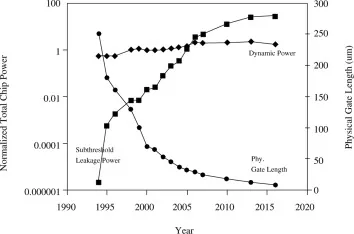
Ignoring leakage current is a frequent oversight. People often assume dynamic power is the only draw, but static leakage accounts for a growing percentage of total power in small-node chips. You must add the static power calculated from the datasheet’s quiescent current to get an accurate total. If your process node is below 28nm, leakage often exceeds 30% of your total budget.
Miscalculating activity factors is another trap. Assuming a switching factor of 1.0 for all logic gates leads to unrealistic power projections that waste design effort. Use simulation tools like ModelSim to observe real switching patterns in your specific code. A toggle rate of 0.1 is standard for most control logic, while data paths rarely exceed 0.5.
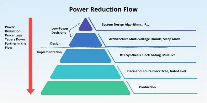
Neglecting voltage scaling creates bloated hardware. Designers often calculate power based on the maximum rated voltage rather than the actual operating voltage. This results in an over-engineered power supply that’s heavier and more expensive than necessary. If your system operates at 0.9V instead of a 1.2V peak, you reduce power consumption by nearly 40% due to the square-law relationship.
Related guides
- Best Power Station for Home in 2026
- How to Fix Power Recliner Stuck in Open Position: Easy Steps
- 10 Best Home Generators for Power Outages: Our Top Picks in 2026
Frequently asked questions
Can I calculate dynamic power without a datasheet?
No, you can’t get an accurate result without the load capacitance value found in the manufacturer’s datasheet. Without this specific constant, you’re guessing at the internal physical properties of the silicon. If you don’t have the datasheet, you must measure the total current draw using a precision ammeter while the chip runs at a known frequency and voltage.
Why does voltage have a squared impact?
Voltage is squared because the charge required to switch a capacitor is proportional to voltage, and the energy per switch is proportional to the square of voltage. Since power is energy divided by time, the voltage remains squared in the formula. This is a fundamental physical property of CMOS logic where the energy stored in the gate capacitance is equal to one-half C times voltage squared.
How often should I re-calculate power?
You should re-calculate power every time you change the operating frequency or the voltage settings in your firmware. Even small adjustments to the clock speed require a new calculation to ensure you stay within the thermal design power of your cooling system. Any change to the input voltage requires an immediate update to your power budget to prevent hardware failure.
Is it safe to run chips at maximum power?
It’s safe only if your cooling solution is rated for the thermal design power of the chip. Running at maximum power for extended periods without adequate heat dissipation will trigger thermal throttling or permanent silicon degradation. Always ensure your heatsink or fan setup matches the wattage output calculated from your power formula.
What happens if the activity factor is wrong?
If your activity factor is too low, your power supply might not provide enough current, causing the system to crash or reboot under heavy loads. If it’s too high, you might over-provision your power delivery system, leading to unnecessary costs and larger component footprints. Always use statistical averages from your software workload to estimate the activity factor accurately.
How does frequency affect power consumption?
Frequency has a linear relationship with dynamic power, meaning if you increase the clock speed by 20%, the dynamic power consumption also increases by 20%. This assumes the voltage remains constant during the frequency change. If you must increase the voltage to maintain stability at higher frequencies, the power consumption will rise much faster than the frequency change alone.
Conclusion
As technology evolves, we’ll continue to see even smaller, more efficient designs that push these limits further. You shouldn’t feel overwhelmed by the math, as modern software tools handle most of the heavy lifting for you. It’s a great time to explore simulation programs that let you test these changes yourself.
