
Identifying star and delta motor terminal connections involves matching the internal motor windings to the external power supply configuration by examining the terminal block layout and the motor nameplate. The physical arrangement of these terminals typically dictates whether the motor is wired in a Wye (Star) or Delta pattern, which fundamentally alters the voltage and current characteristics of the electrical machine. By systematically verifying the continuity between these terminals using a multimeter, you can confirm the internal winding paths and ensure the motor operates safely within its designed voltage rating.
Key Takeaways
- Always verify the motor nameplate for dual-voltage ratings before attempting any wiring changes.
- Use a high-quality multimeter set to low-resistance mode to map the internal winding pairs.
- Ensure the power supply is completely locked out and tagged out prior to touching any terminals.
- Star connections require a neutral or common point, whereas Delta connections create a closed-loop circuit.
- Incorrect wiring can cause immediate winding damage, excessive heat, or rapid motor failure.
How to identify star and delta motor terminal connections
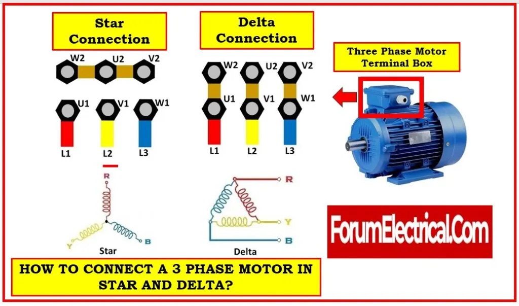
Identifying the configuration requires understanding the standard terminal arrangement, which usually features six connection points labeled U1, V1, W1 and U2, V2, W2. In a standard terminal box layout, these are arranged so that the start of one winding and the end of another can be bridged easily.
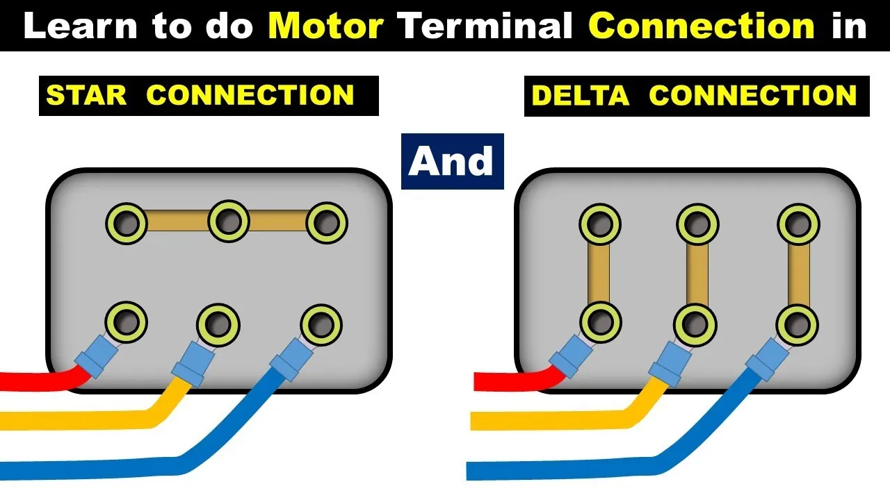
To determine the connection, you must trace which terminals are currently linked by metal strips or jumpers. If the jumpers connect U2, V2, and W2 together, the motor is in Star configuration. If the jumpers connect U1-W2, V1-U2, and W1-V2, the motor is in Delta configuration.
Understanding the Winding Pairs
Before connecting any power, you must identify which terminal pairs represent the individual windings. Using a multimeter, measure the resistance between the terminals. You’ll find three distinct pairs that show low resistance, indicating the internal coils. These pairs are typically labeled U1-U2, V1-V2, and W1-W2. If you don’t have clear markings, you must physically label these pairs to prevent winding phase reversal, which would cause the motor to run in the wrong direction or fail to start.
| Connection Type | Terminal Bridge Pattern | Voltage Application |
|---|---|---|
| Star (Wye) | U2, V2, W2 linked | Higher Voltage |
| Delta | U1-W2, V1-U2, W1-V2 | Lower Voltage |
| Open Loop | No jumpers installed | Diagnostic Phase Only |
Why is winding resistance testing critical?
Resistance testing is the only way to confirm the integrity of the motor internals before applying high-voltage power. Every winding pair should exhibit identical resistance values; a significant deviation in one pair compared to the others suggests a shorted winding or an open circuit.
If you measure resistance between two terminals that shouldn’t be connected, you have likely identified a fault. Using NEMA Standards Publication MG 1 as a reference, technicians follow strict guidelines to ensure that insulation resistance meets minimum safety thresholds before commissioning any motor.
What are the primary motor terminal markings?
Standard motors follow specific labeling conventions to ensure global compatibility. The terminals are almost universally marked as follows:
- U1, V1, W1: These are the start points of the three internal phases.
- U2, V2, W2: These are the end points of the three internal phases.
- PE: The Protective Earth connection, typically colored green or yellow.
- Auxiliary: Sometimes present for thermal sensors or space heaters.
Terminal identification labels are often embossed into the plastic terminal block or printed on a metal tag attached to the motor housing. Never rely on the color of the wires alone, as these can vary depending on the manufacturer or regional wiring standards.
How do you bridge the terminals safely?

Bridging the terminals is the physical act of connecting the copper links or busbars to create the desired electrical circuit. For a Star connection, you must place the three linking bars across the U2, V2, and W2 terminals. For a Delta connection, you must orient the bars vertically to connect U1 to W2, V1 to U2, and W1 to V2.
Warning: Ensure that the busbars are tightened to the torque specification provided by the manufacturer to prevent arcing and overheating at the connection points. Loose connections are the leading cause of terminal block melting in industrial motor applications.
Is there a visual method for identification?
You can often identify the configuration by looking at the orientation of the copper links. In a Star setup, the links appear as a single horizontal or vertical bridge connecting three adjacent terminals.
In a Delta setup, the links appear as parallel lines connecting the top row to the bottom row in an offset pattern. If you see six wires entering the box without any clear linking, the motor might be pre-wired for a specific voltage, or it might be a dual-voltage motor requiring an external starter.
Common Motor Brands and Configurations
- Siemens: Uses standard IEC terminal block layouts.
- Baldor: Often utilizes color-coded leads instead of a terminal block.
- WEG: Frequently includes a detailed wiring diagram inside the terminal box cover.
- ABB: Employs modular terminal blocks that allow for easy jumper changes.
Troubleshooting common connection mistakes
If a motor hums but fails to rotate, you may have a phasing error or a disconnected winding. First, check the continuity of all three phases. If one phase is open, the motor will experience a single-phasing condition, which will trip the thermal overload relay almost immediately. If the motor draws excessive current but runs, you may have accidentally wired a Delta motor in a Star configuration, or vice versa, causing a voltage mismatch.
| Symptom | Potential Cause | Verification Step |
|---|---|---|
| Excessive Heat | Overload or Wrong Config | Check Nameplate Amperage |
| Motor Hums/No Spin | Single-phasing | Check Phase-to-Phase Continuity |
| Wrong Direction | Phased incorrectly | Swap any two power leads |
| Tripping Breaker | Internal Short | Perform Megger Test |
Warning signs of damaged terminal blocks
The terminal block is a high-stress component. If you observe discoloration, charring, or a burnt plastic smell, the terminal block must be replaced. A compromised terminal block can lead to phase-to-phase shorts, which are catastrophic for the motor windings. Always check for loose fasteners or cracked ceramic insulators during your routine maintenance cycles.
Importance of the motor nameplate
The nameplate is your primary authority for all connection data. It explicitly states the voltage ratings for both Star and Delta configurations, such as “400V Y / 230V Delta.” If you apply 400V to a Delta-configured winding rated for 230V, you’ll destroy the motor insulation within seconds. Always document the nameplate data before making any changes to the terminal setup.
Related guides
- What are the different types of branch connections
- Turtle Beach Transmitter Not Working: 5 Fixes for Connection
- Cuisinart Grinder Not Working: Simple Fixes for Motor Issues
Frequently Asked Questions
What happens if I connect a motor incorrectly?
Connecting a motor incorrectly usually results in either immediate failure or severe operational issues. If you wire a Delta motor in Star, it will run at reduced torque and speed, potentially overheating. Conversely, wiring a Star motor in Delta when the voltage is too high will lead to excessive current flow, causing the insulation to break down and the windings to burn out rapidly.
Can I change a motor from Star to Delta?
You can change a motor configuration only if the nameplate specifies dual-voltage capability for both Star and Delta. If the motor is designed strictly for Star operation, attempting to convert it to Delta will result in permanent damage. Always verify the motor’s internal winding design before attempting any reconfiguration, as some motors are permanently connected internally at the factory and can’t be changed.
How do I identify the phases without a diagram?
If the diagram is missing, you must use a multimeter to map the six leads. Find the three pairs of windings by checking for continuity. Once identified, you can label them U1-U2, V1-V2, and W1-W2. Use a low-voltage battery test or a dedicated phase rotation meter to determine the polarity of these windings if you need to ensure the motor runs in a specific direction.
Why do some motors have nine or twelve leads?
Motors with nine or twelve leads are typically designed for multi-voltage operation or reduced-voltage starting, such as Part Winding or Wye-Delta starting. These configurations allow for flexible starting currents and different voltage levels. Identifying these requires a specific connection diagram provided by the manufacturer, as the complexity of the internal wiring makes manual tracing significantly more difficult than with a standard six-lead motor.
Is it safe to test motor terminals while powered?
Never attempt to test or change motor terminal connections while the power is connected. Even if the motor isn’t running, the terminals remain energized and pose a severe risk of electric shock. Always use a lock-out/tag-out procedure to ensure the power source is disconnected and verified as dead before opening the terminal box or touching any internal components.
Conclusion
When you have finished identifying the terminals and confirming the configuration, ensure all connections are tightened and the terminal box cover is securely replaced to prevent moisture or dust ingress. If you’re uncertain about any part of the process, consult the manufacturer’s manual or contact a certified electrician to perform the work. Taking these precautions protects your equipment and ensures a long, reliable service life for your motor.
