
Mechanical linkages offer the advantage of transferring motion and force reliably without electronic sensors or complex software. The disadvantage is that they cannot change behavior on the fly, making digital actuators a better choice for systems requiring frequent modification.
Comparing common mechanical motion systems
The following table highlights how different systems perform in terms of durability, complexity, and setup time. These values assume standard industrial or hobbyist applications; for specialized aerospace or medical equipment, the tolerances and maintenance intervals will be significantly tighter.
| Method | How long | Effort | Cost | Best for |
|---|---|---|---|---|
| Four-bar linkage | Permanent | High | Low | Simple, repetitive paths |
| Cam and follower | Long-term | Medium | Medium | Specific timing cycles |
| Hydraulic linkage | Moderate | High | High | High-force applications |
| Servo system | Short-term | Low | High | Flexible, variable movement |
Choose a four-bar linkage only when your path remains fixed for the life of the machine. If you must adjust the trajectory later, the cost of re-machining the steel arms often exceeds the price of a programmable servo.
Use hydraulic systems when your load exceeds 500 pounds of constant force. Below this threshold, consider if the complexity of hydraulic maintenance outweighs the benefits of the system.
If your application requires sub-millimeter precision, avoid cam systems entirely. Cams suffer from mechanical wear that introduces backlash after roughly 5,000 hours of operation. In these cases, a closed-loop servo system is the only way to maintain accuracy as components age.
Always calculate your duty cycle before selecting a drive. If the system runs more than 12 hours a day, prioritize the lower maintenance requirements of mechanical linkages over the ease of electronic control. You’ll trade initial setup speed for years of reliable, hands-off operation.
The four-bar linkage system
A four-bar linkage uses four rigid bodies connected by joints to transform input motion into a specific output path. It’s the most fundamental mechanism for converting rotary motion into oscillating or reciprocating movement.
- Calculate the link lengths to ensure the Grashof condition is met, which determines if the shortest link can fully rotate.
- Machine the pivot points using high-grade steel or bronze bushings to minimize friction and wear over time.
- Apply a high-pressure lubricant to all joints to prevent metal-on-metal seizing during operation.
- Test the range of motion by hand before attaching any high-torque motors to ensure there’s no mechanical interference.
This method is excellent for high-load tasks where durability is the priority. Its main weakness is the lack of flexibility; changing the output path requires physically machining new parts.
The cam and follower mechanism

Cams are used when you need a specific, non-linear output motion that a simple linkage can’t replicate. By changing the shape of the cam, you can force the follower to dwell, accelerate, or move backward at precise intervals.
- Design the cam profile using CAD software to map the exact timing of each movement phase.
- Use a hardened steel or acetal plastic for the cam surface to resist deformation under pressure.
- Install a return spring on the follower to ensure constant contact with the cam profile throughout the entire rotation.
- Verify the contact pressure between the roller and the cam to prevent surface pitting.
This design is perfect for high-speed automated assembly lines where timing is everything. A significant disadvantage is the high wear rate at the contact point, which often requires frequent inspection and lubrication to maintain precision.
Hydraulic and pneumatic linkages
Fluid-based linkages use pressurized oil or air to transmit force over distances where rigid rods would be too heavy or bulky. These systems excel in heavy machinery like excavators or hydraulic presses.
- Size the cylinders based on the force requirements, accounting for the system pressure measured in PSI.
- Install flexible hoses with compatible fittings rated for the maximum expected system pressure.
- Bleed the air out of the lines to ensure the motion is smooth and responsive.
- Add a pressure relief valve to prevent component failure during sudden load spikes.
These linkages are unmatched for lifting massive loads with high power density. The primary downside is the risk of leaks, which can contaminate the workspace and lead to a total loss of system pressure.
Choosing the right mechanical system
When you’re in a hurry, the four-bar linkage is the winner because it uses simple, easily sourced components that require minimal calibration. If you’re doing this for the first time, a cam system is often easier to debug because the timing is visible and locked into the physical shape of the cam. When you want the best possible result regardless of the effort required, hydraulic systems are superior because they offer the highest force-to-weight ratio and can handle extreme environments.
Remember that mechanical linkages are a trade-off between simplicity and flexibility. If you pick a rigid linkage, you gain longevity and power but lose the ability to change your mind later. If you choose a software-based system, you gain infinite programmability but introduce points of failure like short-circuits or software bugs.
Rules for reliable mechanical motion
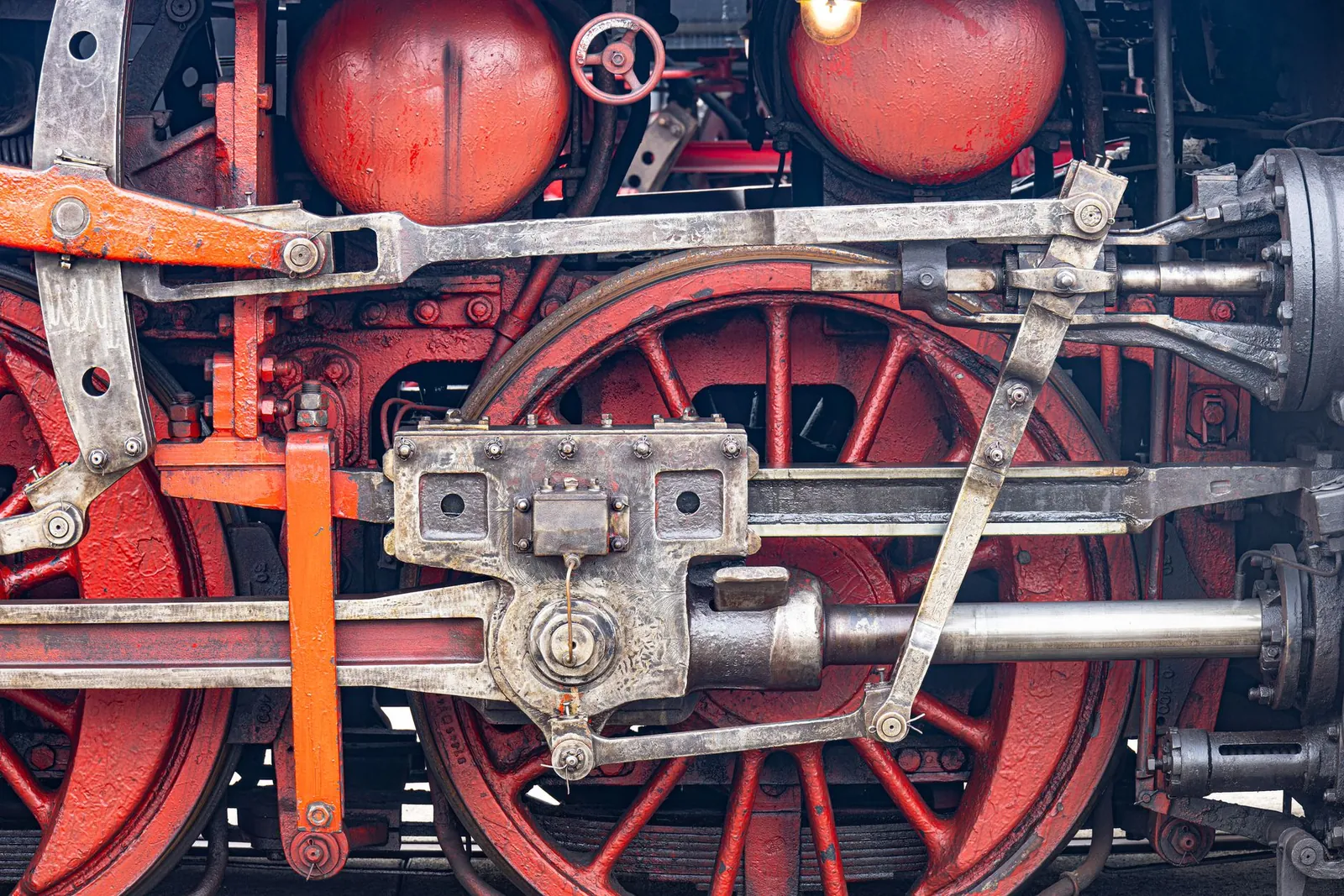
Regardless of the system you select, you must adhere to basic engineering principles to ensure your machine functions correctly. Start by defining your load requirements, as this dictates the material strength needed for your pivots and rods. Always check your joints for play or “slop” halfway through your project; even a millimeter of movement in a joint can lead to catastrophic failure once the machine is under a full load.
If your application involves high-speed movement or heavy loads, consult with a professional mechanical engineer to ensure your design meets local safety regulations. Designing linkages that involve high-speed rotation or heavy lifting carries a risk of injury if parts fail, so always prioritize the use of safety guards and fail-safe stops.
Frequently asked questions
How long do mechanical linkages last?
They can last for decades if the joints are properly lubricated and kept free of debris. The lifespan depends entirely on the material hardness and the frequency of use, so check the manufacturer’s data sheets for the specific wear ratings of your pivot materials.
Is it safe to build my own linkage system?
Yes, it’s safe as long as you use appropriate safety guards to protect against pinch points. If you’re working with high-pressure hydraulics or heavy swinging arms, you must follow the safety guidelines for mechanical power transmission to avoid injury.
What happens if a linkage breaks during operation?
The machine will likely lose its timing or stop moving entirely, which can cause internal damage to the drive motor. If you notice strange vibrations or grinding noises, shut the system down immediately to prevent the failure from destroying other parts of the assembly.
How much maintenance do these systems need?
They require inspection every 100 to 500 hours of operation depending on the load and environment. You should check for loose fasteners, replace worn bushings, and reapply grease to ensure the motion remains smooth and accurate.
Can I replace a mechanical linkage with a motor?
Yes, you can replace a linkage with a servo motor if you need more control over the motion path. However, you’ll lose the mechanical advantage and reliability that a direct physical linkage provides for heavy-duty tasks.
Why is my linkage vibrating?
Vibration typically stems from loose joints or imbalanced rotating parts. Tighten all pivot points and ensure your cam or crank is perfectly centered to eliminate excess movement. This simple adjustment restores stability and prevents further mechanical wear, though you should inspect the components periodically to ensure they remain secure over time.
Conclusion
Ultimately, your choice depends on the specific needs of your project. If you prioritize simplicity and durability, these rigid systems won’t let you down. As you move forward, try sketching out your desired path of motion on paper; it’s a great way to see if a simple design will work for you.
