
The moment of inertia matrix is a 3×3 symmetric array that captures how a rigid body’s mass spreads around three perpendicular axes. It links angular velocity to angular momentum in 3D rotation, and you’ll find it in every dynamics textbook under the name “inertia tensor.” If your object spins around just one fixed axis, you don’t need the full matrix — a single scalar value works fine.
Moment of inertia matrix basics
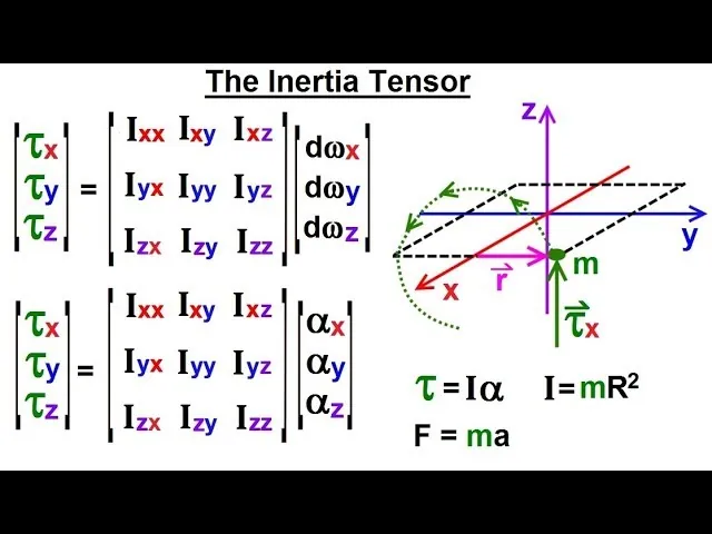
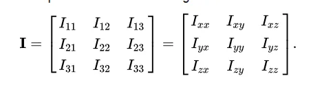
- It’s a 3×3 grid of nine numbers describing rotational resistance around three axes.
- The three diagonal entries are the moments of inertia about the x, y, and z axes.
- The six off-diagonal entries are products of inertia, and they always appear in equal pairs.
- For any solid shape, you can rotate the coordinate system until all off-diagonal terms hit zero.
- Those special axes where the off-diagonals vanish are called the principal axes of the body.
- Check a modeled body’s values by reading its mass distribution or checking its CAD software properties.
Why the matrix has off-diagonal terms
A single number describes rotation only when the spin axis matches the object’s natural balance. Real objects rarely spin that neatly. When an object rotates around an arbitrary axis, its mass pulls unevenly. That imbalance creates torques along directions you didn’t push. The off-diagonal terms capture exactly this cross-axis coupling.
Without those terms, you’d predict the wrong forces on bearings and mounts. A spinning wheel tilted slightly off its axle shakes violently because of them. The math reflects physical reality: angular momentum doesn’t always point the same way as angular velocity. They align only along the principal axes.
The diagonal elements measure resistance to spinning directly around each coordinate axis. Think of them as three separate flywheels built into one body. The off-diagonal elements measure how much spinning around one axis drags the other two along. If your shape is perfectly symmetric about a plane, the product of inertia for axes in that plane drops to zero.
This isn’t just theory for textbooks. Engineers designing turbines, satellites, or car crankshafts must calculate these values before manufacturing begins. MIT’s OpenCourseWare rigid body dynamics notes explain how the tensor governs Euler’s equations of motion for rotating bodies. Skipping this step means guessing at vibration frequencies, and guesses cost money when parts fail.
If it’s a solid block, all six off-diagonals might carry weight. You trade simplicity for accuracy here: assuming zero off-diagonals speeds up hand calculations but hides dangerous imbalances in fast-spinning parts.
When the matrix changes
The numbers inside the grid aren’t fixed properties of the object alone. They shift whenever your reference frame shifts. Moving the origin or tilting the axes rewrites every entry.
| Situation | What changes | What to do instead |
|---|---|---|
| Origin moves away from center | Diagonal values increase; off-diagonals shift | Apply parallel axis theorem |
| Axes rotate relative to body | Diagonals and off-diagonals mix | Use rotation transformation matrix |
| Body deforms during operation | Mass distribution shifts continuously | Recalculate at each time step |
| Object has symmetry plane | Matching products become zero | Align axes with symmetry planes |
| Spinning near principal axes | Off-diagonal effects stay small | Single-axis approximation works safely |
| High-speed unbalanced rotor | Cross-coupling forces grow rapidly | Full tensor analysis becomes mandatory |
How to build the matrix
You’re building a 3×3 grid where each cell holds either an integral over volume or a sum over discrete masses. This assumes standard SI units; if you’re working in imperial pounds and inches, convert your final answers to slug-feet² or keep everything consistent throughout.
- Pick your coordinate origin at the body’s center of mass, because starting anywhere else inflates every term and forces extra correction steps later.
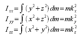
- Write down the three diagonal formulas: Ixx equals the integral of (y² + z²) dm, and repeat cyclically for Iyy using (x² + z²) and Izz using (x² + y²).
- Calculate each diagonal term by integrating across the entire volume, or summing m times r-squared for each discrete point mass if you’re modeling particles.
- Compute the six off-diagonal products using negative integrals: Ixy equals negative integral of x times y dm, and remember that Ixy always equals Iyx by definition.
- Arrange your nine computed values into a symmetric grid with diagonals on the main line and matching products mirrored across it.
- Verify symmetry by checking that every element above the diagonal matches its partner below it, which confirms you haven’t dropped a negative sign.
- Find eigenvalues of this matrix if you need principal moments, since those three numbers tell you the pure rotational resistance without cross-axis drag.
- Validate your result by confirming all diagonal entries are positive and no single product of inertia exceeds the geometric mean of its two related diagonal terms.
Mistakes that ruin the calculation
- Dropping the negative sign on products of inertia flips the direction of predicted gyroscopic torques, leading to bearings that fail weeks early instead of lasting years.
- Integrating from a corner instead of the center of mass adds extra inertia via the parallel axis theorem, leading to oversized motors and wasted resources.
- Assuming all off-diagonals are zero for a complex shape ignores real imbalance, causing vibrations that shake assemblies apart at operating speed.
- Mixing units between mass points — grams for some, kilograms for others — corrupts the entire matrix silently, producing numbers that look right but predict wrong behavior.
- Forgetting that the matrix depends on axis orientation means copying textbook values into a model with rotated coordinates, guaranteeing simulation errors from the first frame.
Related guides
- 10 Best Phosphate Removers to Keep Your Pool Clear in 2026
- Best Drain Unblockers: How to Clear Clogs Effectively in 2026
- 8 Perfect Weekly Pool Chemical Reviews for Clear Water in 2026
Frequently asked questions
Can the matrix have negative values?
Yes, the off-diagonal entries are frequently negative depending on how mass sits relative to your chosen axes. The diagonal elements, representing pure rotational resistance, are always strictly positive for any physical object containing actual mass. Negative diagonals would imply imaginary mass, which doesn’t exist outside theoretical math problems.
Why does symmetry matter for inertia?
Symmetry kills off-diagonal terms automatically. If your object has a plane of symmetry and you align one axis within it, the products involving the perpendicular axis become exactly zero. This cuts your work from nine calculations down to six or fewer, and removes cross-axis coupling entirely for those aligned directions.
How long does calculating this take?
For simple shapes like cylinders or boxes, hand calculation takes about five minutes using standard formulas. Complex geometries modeled in CAD software compute the full tensor instantly once you assign material density. The time scales with geometry complexity, not with the math itself, since computers handle the integration.
Is it safe to ignore off-diagonal terms?
Only if your rotation axis aligns closely with a principal axis and speeds stay low. At high RPM, ignored products create unmodeled gyroscopic torques that snap shafts. For slow-moving robotic arms or static structural analysis, dropping them saves effort without risking failure, but verify alignment first.
What happens if the origin isn’t at center of mass?
Every single value grows larger than it should be. The parallel axis theorem lets you correct this by subtracting mass times distance squared, but forgetting that step makes your object appear heavier rotationally. Motors sized to these inflated numbers waste energy and add unnecessary weight to the whole system.
Does the matrix change if the object bends?
Yes, deformation redistributes mass relative to your axes. Flexible structures like aircraft wings or long robot arms need updated matrices at each simulation time step. Rigid body assumptions break down completely here, and using a static matrix for a bending part produces dangerously wrong force predictions.
How many principal axes does a body have?
Exactly three, and they’re always mutually perpendicular regardless of shape. Along these axes, the matrix becomes purely diagonal with zeros everywhere else. Finding them requires solving a cubic eigenvalue equation, but most engineering software outputs them directly when you request principal properties from a solid model.
Is it the same as the inertia tensor?
They’re identical concepts expressed differently. The matrix is simply the tensor written as a 3×3 grid of numbers for a specific coordinate frame. Change the frame and the numbers change, but the underlying physical property — how mass resists rotation — stays constant. Tensors are frame-independent; matrices are their snapshots.
Conclusion
The matrix gives you the complete rotational picture of any solid object, but it only holds true for the exact coordinate system you built it in. Read your values directly from the diagonal when your axes match the principal directions, and check your CAD tool’s mass properties panel to see what your specific geometry actually produces.

1 thought on “What Is the Moment of Inertia Matrix: A Clear Guide”