
Sensors serve as the fundamental bridge between the physical world and digital systems, acting as the primary input devices for everything from industrial robotics to your smartphone. When looking for a complete guide to sensors, it’s important to recognize that these components don’t merely “see” or “hear”; they transduce environmental stimuli into readable electrical signals. Whether you’re designing a custom circuit or integrating off-the-shelf automation hardware, understanding how to select, calibrate, and deploy these devices is essential for any modern electronics project.
Key Takeaways
- Identify the specific physical variable you need to measure before selecting your sensor technology.
- Always check the output signal type—analog or digital—to ensure compatibility with your microcontroller or PLC.
- Consider the operating environment, specifically temperature ranges and moisture levels, to prevent signal degradation.
- Perform regular calibration to maintain accuracy and reliability in long-term sensing applications.
- Prioritize power efficiency if your device relies on battery life for remote operation.
How Do Sensors Work?
At their core, sensors function via signal transduction. They convert a physical input—such as pressure, light, or temperature—into a measurable electrical output. This process typically involves a sensing element that changes its electrical properties, such as resistance or capacitance, in direct response to environmental changes. This raw change is then processed by an internal circuit to provide a stable, readable signal.
The Role of Transducers
A transducer is the broader category that includes sensors. While a sensor detects a variable, a transducer converts energy from one form to another. In practice, most modern sensors integrate both the sensing element and the signal conditioning electronics on a single chip, making them ready for direct connection to digital processors.
Categorizing Different Sensor Types
Sensors are generally classified by the physical property they monitor. Selecting the right category is the first step in any engineering design process.
| Sensor Category | Typical Input Variable | Common Application |
|---|---|---|
| Thermal | Temperature | Thermostats, HVAC systems |
| Proximity | Distance/Presence | Industrial assembly lines |
| Optical | Light Intensity | Automatic street lighting |
| Pressure | Force per area | Tire pressure monitors |
| Chemical | Gas concentration | Carbon monoxide detectors |
Understanding Active vs Passive Sensors
Sensors are further divided into active and passive classifications. Active sensors require an external power source to operate and often emit energy, such as ultrasonic pulses or infrared light, to measure the environment. Passive sensors, by contrast, don’t require an external power supply to detect the stimulus; they directly convert the physical energy into an electrical signal, such as a thermocouple producing a voltage from a temperature gradient.
Selecting the Right Hardware
When choosing components, you must balance sensitivity, range, and cost. High-precision instruments often come at a premium, while general-purpose sensors are sufficient for most hobbyist projects.
- Temperature: Thermistors, thermocouples, and digital sensors like the DS18B20.
- Proximity: Infrared (IR) distance sensors, ultrasonic modules, and inductive sensors for metal detection.
- Light: Photodiodes, photoresistors (LDRs), and ambient light sensors.
- Motion: PIR sensors for human detection and MEMS accelerometers for tilt or vibration.
What Are Common Sensor Costs?
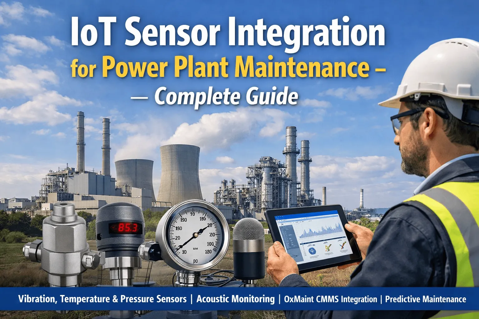
The price of hardware varies based on precision and application. For basic prototyping, individual sensors typically cost between $1.50 and $12.00. For industrial-grade, ruggedized sensors designed for factory environments, expect to pay between $45.00 and $350.00 per unit depending on the material and certification requirements.
How to Integrate Sensors Effectively
Integration requires careful attention to the data interface. Most modern sensors communicate using established protocols such as I2C, SPI, or UART. Always ensure your microcontroller has the necessary pins and library support before committing to a specific component.
Managing Signal Noise
Electronic noise is the primary enemy of data accuracy. Long wires, electromagnetic interference from motors, and poor grounding can corrupt your signal. Use shielded cables and decoupling capacitors near the power pins of your sensor to maintain signal integrity.
Troubleshooting Common Sensor Issues
When a sensor fails to provide data, follow a systematic approach to isolate the fault. Start by checking the power supply voltage with a multimeter. If the power is stable, verify the data line connections and ensure your code is correctly addressing the sensor’s unique hardware ID.
| Issue | Potential Cause | Fix |
|---|---|---|
| No Data Output | Loose wiring or no power | Re-check connections and VCC pins |
| Erratic Readings | Signal noise or interference | Add a capacitor or shield cables |
| Drift Over Time | Aging or environmental stress | Re-calibrate the sensor baseline |
| Wrong Values | Incorrect scaling or library | Verify data sheet conversion math |
Calibration and Maintenance
Calibration is the process of comparing your sensor’s output against a known standard. Over time, environmental factors like dust, humidity, or hardware fatigue can cause “drift,” where the sensor’s readings deviate from reality. Establish a regular maintenance schedule to ensure your system remains within the International Organization for Standardization guidelines for precision instrumentation.
Warning: Always isolate the sensor from high-voltage circuits during calibration to prevent permanent damage to your microcontroller or the sensor itself.
Environmental Considerations
Environmental factors are often ignored until the system fails in the field. Humidity, extreme heat, and vibrations can destroy sensitive electronics. If your project is outdoors, use an IP-rated enclosure to protect the hardware.
Choosing the Right Housing
- IP65: Protection against dust and low-pressure water jets.
- IP67: Protection against dust and temporary immersion in water.
- Hermetic: Completely sealed, often used in high-pressure or vacuum environments.
Data Conversion and Processing
Raw data from a sensor is rarely useful in its initial state. You’ll likely need to perform analog-to-digital conversion (ADC) or apply a mathematical filter. A simple moving average filter can smooth out jittery data, while a Kalman filter is preferred for more complex applications involving high-speed motion or noisy environments.
Pro Tip: Use a hardware-based interrupt if you’re monitoring a sensor that triggers an alarm or a time-sensitive event; this prevents your code from missing critical inputs while performing other calculations.
Frequently Asked Questions
Which sensor is best for beginners?
The DHT11 or DHT22 temperature and humidity sensors are ideal for beginners. They’re inexpensive, easy to find, and feature simple digital interfaces that require very few external components to function. They allow you to practice reading data and displaying it on an LCD or serial monitor without needing complex signal conditioning or advanced programming knowledge, making them a staple in introductory electronics learning kits.
How do I connect a sensor?
Connecting a sensor involves three main steps: providing power, establishing a data connection, and writing software. First, connect the VCC and GND pins to your microcontroller’s power rails. Next, connect the output or communication pins (like SDA/SCL for I2C) to the corresponding ports on your board. Finally, upload code using the appropriate library to read and interpret the incoming electrical signals.
What is signal conditioning?
Signal conditioning is the process of preparing a sensor’s raw output for a controller. Since raw sensor signals are often too weak, noisy, or in the wrong voltage range, conditioning circuits—such as amplifiers, filters, and bridges—are used to boost the signal and remove interference. This ensures the microcontroller receives a clean, readable voltage level that accurately represents the physical variable being measured.
Why are my sensor readings fluctuating?
Fluctuating readings are usually caused by electromagnetic interference (EMI) or poor power supply regulation. Ensure your sensor wires are short and away from high-current lines like motors. Adding a small capacitor between the VCC and GND pins of the sensor can filter out power spikes. If the problem persists, ensure your code includes a software-based filter to average out the rapid, jittery variations in the signal.
Can I calibrate a sensor at home?
Yes, you can calibrate many sensors at home by comparing them to a known reference. For temperature sensors, use an ice-water bath for 0°C and boiling water for 100°C. For distance sensors, use a tape measure to verify accuracy at specific intervals. While not as precise as laboratory-grade equipment, this process helps you create an offset or scaling factor in your code to improve accuracy.
Conclusion
Now that you understand the fundamental principles and selection criteria for sensors, your next step is to obtain a common, low-cost sensor like a temperature or light module and integrate it into a breadboard circuit. By reading real-time data into your microcontroller, you’ll gain the practical experience needed to scale your designs into more complex, automated systems.
