
A radius of gyration is the distance from an axis where the entire mass of an object could be concentrated without changing its rotational inertia. You find this value by taking the square root of the ratio of the moment of inertia to the object’s total mass. This mathematical property simplifies complex rotational dynamics into a single, manageable distance for engineering design.
Defining the radius of gyration
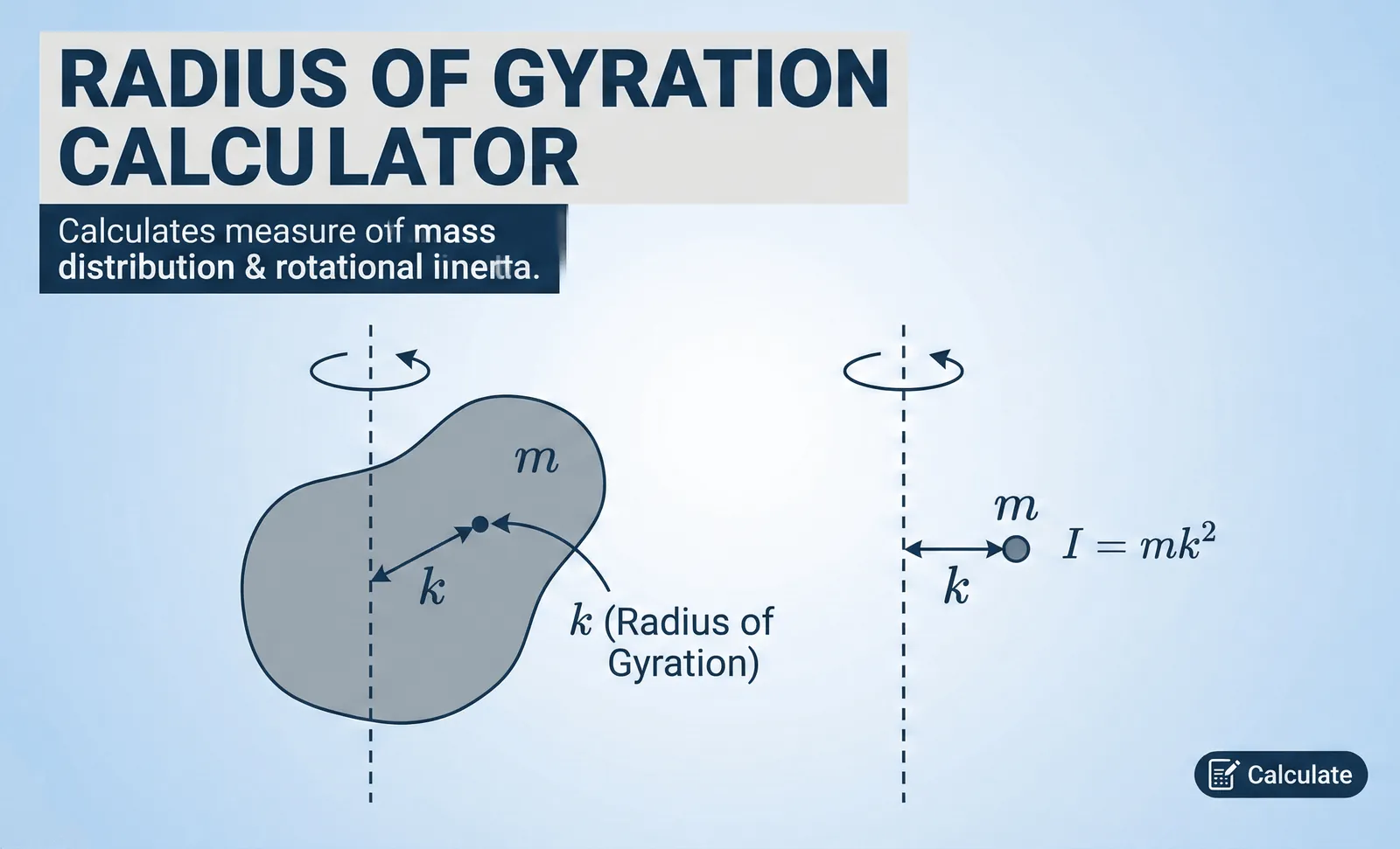
The radius of gyration describes how mass sits relative to a rotation point. If you have a solid disk and a hollow ring of the same mass, the ring has a larger radius of gyration because its mass is further from the center. This explains why the ring is harder to start or stop spinning compared to the solid disk.
Engineers use this value to predict how structures like beams or shafts will resist bending under pressure. By condensing the shape into a point mass, you make calculations for stress and vibration much faster. This assumes the object is rigid; for flexible or complex assemblies, you must account for the specific geometry and material density throughout the structure.
If you’re calculating for a simple shape, you can use standard geometric formulas. If the shape is irregular, you might need to use a numerical integration or experimental testing to find the moment of inertia first.
Quick reference for rotational properties
The radius of gyration represents the distance from an axis where you can concentrate the entire mass of an object without changing its moment of inertia. Calculate it using $k = \sqrt{I/m}$, where $I$ is the moment of inertia and $m$ is the total mass.
Always express this value in units of length, typically meters or inches. Engineers rely on this metric to determine the buckling strength of structural columns and beams. If the radius of gyration is high, the object resists angular acceleration more effectively because its mass is distributed further from the pivot point.
Compare shapes carefully. A solid cylinder always yields a smaller radius than a thin-walled pipe of equal mass. If you assume these values are interchangeable, you’ll underestimate the torque required for rotation. Use the solid cylinder constant for compact objects, but switch to the pipe formula for hollow, lightweight structures.
Why mass distribution matters for rotation
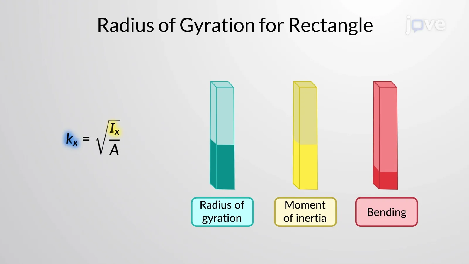
The primary reason to use this value is to simplify the complex math of rotating bodies. Instead of calculating the contribution of every tiny particle in a machine part, you treat the whole object as a single point at distance $k$ from the rotation axis. This shortcut is the foundation for most mechanical design calculations involving shafts and flywheels.
If the mass is concentrated near the axis, the radius of gyration is small, leading to low rotational inertia. If the mass is pushed outward, the value increases, making the object “heavier” to turn. This is why a figure skater pulls their arms in to spin faster; they’re effectively decreasing their own radius of gyration to reduce their resistance to rotation.
This property isn’t just for spinning objects; it’s vital for structural engineering. When you look at how a steel beam resists buckling, the radius of gyration tells you how effectively the cross-sectional area is placed to prevent bending. If you double the distance of the material from the center, the resistance to bending doesn’t just double; it increases significantly based on the square of that distance.
Situations requiring different calculations
The standard formula $k = \sqrt{I/m}$ works for most rigid objects, but specific conditions change how you approach the math.
| Situation | What changes | What to do instead |
|---|---|---|
| Complex shapes | Geometry is irregular | Use CAD software for $I$ |
| Multiple parts | Combined mass distribution | Sum the individual inertias |
| Non-uniform density | Mass isn’t even | Use integral calculus methods |
| Dynamic loading | Forces change over time | Account for transient inertia |
| Flexible structures | Material deforms | Use finite element analysis |
How to calculate the value properly
- Identify the axis of rotation for the object. This is the line around which the object spins or bends.
- Calculate the moment of inertia ($I$) for the object. For simple shapes like spheres or cylinders, use standard reference tables to find the formula for your specific axis.
- Determine the total mass ($m$) of the object. Use a scale for physical objects or calculate it using the material volume and density.
- Divide the moment of inertia by the total mass ($I / m$). Ensure your units are consistent; if $I$ is in $kg \cdot m^2$, your mass must be in $kg$.
- Take the square root of the resulting value. This result is your radius of gyration ($k$).
- Verify the result by checking that the value is smaller than the physical radius of the object. If it’s larger, re-check your moment of inertia formula.
Mistakes that ruin your calculations
- Mixing units: Using inches for mass and feet for inertia creates a wrong result that can lead to structural failure.
- Wrong axis: Using the moment of inertia for a center axis when the object rotates on an edge will give you the wrong value.
- Ignoring density: Assuming a part is solid when it has internal hollows will lead to an overestimated radius of gyration.
- Rounding too early: If you round the moment of inertia before taking the square root, you lose accuracy in the final design.
Related guides
Frequently asked questions
Does the radius of gyration depend on the material density?
Yes, it depends on the distribution of that density throughout the object. If the material is denser at the edges, the radius of gyration increases, even if the total mass stays the same. You must account for the specific density map of your component to get an accurate measurement.
How long does it take to calculate for a complex part?
It takes a few minutes if you have the right software, but manual calculation can take hours. If you’re using professional CAD software, the system calculates the moment of inertia automatically. For manual work, you must break the part into simple geometric shapes and combine them using the parallel axis theorem.
Is it safe to use an estimated value for construction?
No, you should never estimate this value when designing structures meant to hold weight. Small errors in the radius of gyration lead to large errors in buckling calculations. Always use calculated values from verified engineering tables or precise CAD geometry to ensure the safety of your design.
What happens if the radius of gyration is too low?
A low value means the object has very little resistance to bending or rotation. If a structural column has a low radius of gyration, it’s likely to buckle under a load that it should otherwise support. You must increase the cross-sectional area or move material further from the center to fix this.
Does it matter if the object is hollow?
Yes, a hollow object has a much higher radius of gyration than a solid one of the same mass. Because the mass is located further from the axis, the object’s resistance to rotational change is significantly higher. Always check the specific geometry of your part before choosing a formula.
Can I measure the radius of gyration by hand?
Yes, you can measure it by hanging the object as a pendulum and timing its swing. By measuring the period of the swing and knowing the distance from the pivot to the center of mass, you can calculate the moment of inertia and then solve for the radius of gyration.
Conclusion
The accuracy of your result depends entirely on the precision of your input data regarding mass distribution. If you’re working on a project where safety is a factor, double-check your moment of inertia formula against the physical axis of rotation. Using the wrong axis is the most common cause of errors in structural design.
