
A fixed resistor is an electronic component that provides a constant, unchanging amount of electrical resistance to a circuit. You’ll find that the fixed resistor definition symbol and uses are standardized by the Institute of Electrical and Electronics Engineers to ensure consistency in engineering designs. Its primary purpose is to limit current flow and divide voltages within electronic devices.
Defining the fixed resistor and its symbol
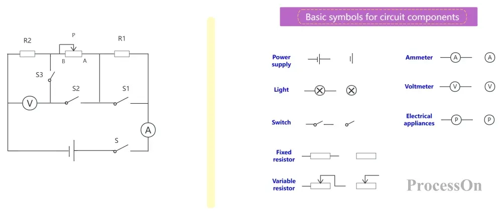
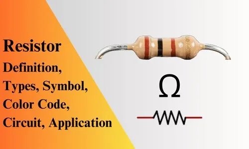
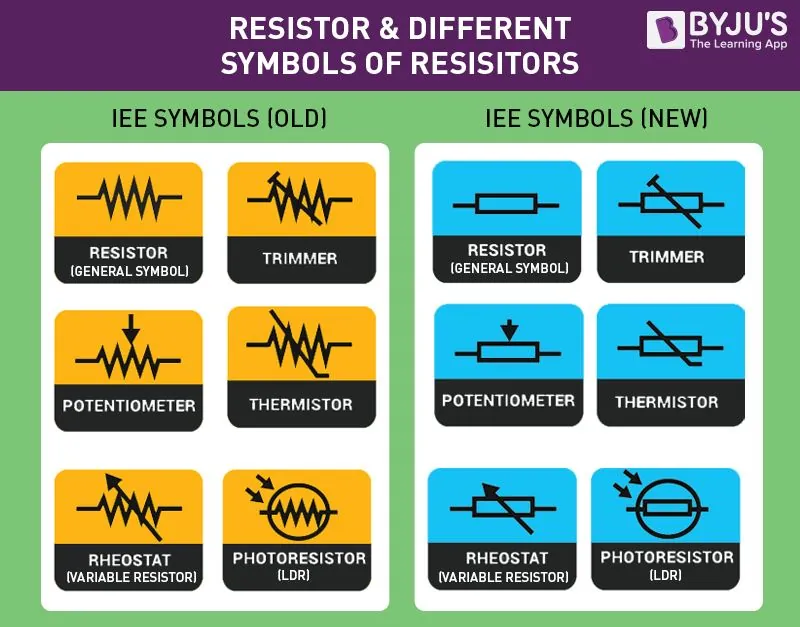
A component symbol for these parts usually appears as a zig-zag line in American circuit diagrams or a simple rectangle in international schematics. These symbols represent the physical obstruction the component presents to the flow of electrons. Because the resistance value is set during the manufacturing process, it doesn’t change based on external environmental factors like heat or light.
You can identify the resistance value of a component by looking at the colored bands printed on its body. These bands follow a specific international code that tells you the value in ohms and the tolerance level. If you’re working on a breadboard, you must ensure the wattage rating is high enough for your circuit. If the current is too high for the rating, the component will overheat and fail.
Quick Facts for Circuit Design
- Resistance remains constant regardless of the voltage applied, provided the component stays within its thermal limits.
- The symbol is a zig-zag line or a rectangular box.
- Power ratings are usually measured in watts; standard small parts are often 0.25 watts.
- Tolerance levels show how much the actual value can vary from the label, typically 1% to 5%.
- These components are polarized only in rare, specialized high-frequency applications, but generally, they’re non-polarized.
Why Resistance Is Necessary
Electrical circuits require precise control over how much current flows through specific paths to prevent damage to sensitive parts. Without this control, components like light-emitting diodes would receive too much power and burn out almost instantly. By inserting a component with a known resistance, you restrict the flow of electrons to a safe level. This process is governed by Ohm’s Law, which states that current equals voltage divided by resistance.
Voltage division is another common reason to use these parts in a design. When you have two or more resistors in a series, the total voltage of the circuit is split across them based on their individual values. This allows engineers to create reference voltages for microcontrollers or sensors from a single power source. It’s a fundamental method for managing signal levels in computers and audio equipment.
The physical construction of these parts varies based on the materials used, such as carbon film, metal film, or wire-wound cores. Metal film versions are preferred for precision work because they offer tighter tolerance levels and create less internal noise than carbon-based types. If your circuit requires high power handling, you would choose a wire-wound version because it can dissipate heat more effectively than smaller film types.
Situations Requiring Different Approaches
| Situation | What changes | What to do instead |
|---|---|---|
| High power needs | Component size | Use wire-wound ceramic resistors |
| Precision circuits | Tolerance levels | Select 0.1% metal film parts |
| High frequency | Inductance effects | Use non-inductive film resistors |
| Tight space | Component footprint | Use surface mount devices |
| Variable needs | Resistance value | Use a potentiometer or trimmer |
When your design exceeds 2 watts, standard carbon film resistors will fail. Switch to wire-wound ceramic units to dissipate heat effectively without burning the board.
For precision, never rely on standard 5% tolerance parts. If your circuit requires a stable voltage reference, use 0.1% metal film resistors to avoid drift.
High-frequency applications demand caution. A standard resistor acts like a small inductor at high speeds, creating unwanted noise. Use non-inductive film resistors to keep your signals clean.
Space constraints often tempt designers to cram components together. If you lack room, shift to surface mount devices (SMD). They reduce parasitic inductance and save significant board real estate.
Finally, if you find yourself swapping parts to tune a circuit, stop. Install a potentiometer. It saves hours of soldering and allows for exact calibration in real time.
How to Install a Resistor Correctly
- Identify the required resistance value using the color code or a multimeter to ensure you have the right part for your specific circuit plan.
- Check the power rating of your component; if your circuit draws more than 0.25 watts, you must use a larger, higher-wattage part to avoid thermal failure.
- Bend the leads of the component at a 90-degree angle so they line up with the holes on your circuit board or breadboard.
- Insert the leads into the board; the direction doesn’t matter because these components aren’t polarized and will function the same in either orientation.
- Solder the leads to the circuit board pads if you’re building a permanent device, ensuring the solder joint is shiny and covers the entire pad.
- Trim the excess length of the leads using wire cutters to prevent them from touching other components and causing a short circuit in your design.
Mistakes That Ruin Your Circuit
Using a resistor with a wattage rating too low for the current causes the component to smoke or burn. Always check the power dissipation by multiplying the square of the current by the resistance. If your calculation exceeds the resistor’s rating by even ten percent, swap it for a higher wattage version to prevent failure.
Misreading color bands leads to a component that restricts too much current and halts your circuit. If the bands appear faded, use a digital multimeter to verify the resistance before soldering.
Touching the body of a part while soldering causes painful skin burns if the circuit has been running. Use needle-nose pliers to hold components in place instead.
Leaving long, untrimmed leads creates accidental short circuits when they bend. Clip leads to within two millimeters of the board to ensure stability.
Related guides
- Foosball Glossary: Key Terms and Definitions Explained in 2026
- Fixed vs Handheld Shower Head: Choosing the Right Style in 2026
Frequently Asked Questions
How do I read the color bands on a resistor?
You read the bands starting from the end closest to the leads, using the first two or three colors to represent digits and the next color as a multiplier, with the final band indicating tolerance. The final band, usually gold or silver, shows the tolerance percentage. Always consult a standard color code chart to ensure you’re reading the correct values for your specific part.
Is it safe to use a resistor with a higher wattage?
Yes, it’s perfectly safe to use a component with a higher wattage rating than your circuit requires. The wattage rating represents the maximum power the part can handle before it sustains damage, so a higher rating simply provides an extra safety margin. It won’t change the resistance value or interfere with the circuit’s operation in any way.
What happens if I use the wrong resistance value?
Using the wrong value will change the amount of current flowing through your circuit, which could stop the device from functioning or damage sensitive parts. If the value is too low, too much current may flow and cause overheating; if it’s too high, the device may not receive enough power to turn on or perform its intended task.
How long do these components last?
They’re designed to last for many years, often outliving the electronic devices they’re installed in. They don’t have moving parts or chemicals that degrade over time, provided they’re operated within their rated voltage and temperature limits. Physical damage or exposure to extreme moisture is usually the only reason they fail prematurely in a standard environment.
Does the orientation of the resistor matter?
No, the orientation doesn’t matter because these components are non-polarized. You can install them in either direction, and they will provide the exact same resistance to the circuit flow. This makes them very easy to work with during assembly, as you don’t need to worry about which lead is the positive or negative side.
How do I check if a resistor is broken?
You can test a component by setting your multimeter to the ohms function and placing the probes on each lead. If the reading matches the expected value based on the color bands, the part is likely functional. If the meter displays “OL,” the internal element has failed and requires replacement.
Conclusion
Whether you’re building a simple hobby project or exploring complex circuits, these components are essential building blocks. They’re reliable and easy to work with, so don’t hesitate to experiment with different values in your next design. You’ll quickly see how they help keep your electronics running safely and exactly as intended.
