
Capacitors are components that store energy in an electric field, and because they block direct current while allowing alternating current to pass, they act as both ac or dc devices depending on the circuit. In a dc circuit, the capacitor charges until it matches the voltage source and then stops current flow. In an ac circuit, the capacitor constantly charges and discharges as the voltage polarity flips, creating a continuous flow of current.
The main factor deciding how a capacitor behaves is the frequency of the source voltage. If you connect a capacitor to a constant dc supply, it acts like an open switch once it reaches full charge. If you connect it to an ac supply, the capacitor’s impedance changes based on the frequency. A common mistake is assuming a capacitor works the same way regardless of the voltage type, which can lead to overheating or component failure.
Managing Capacitor Circuit Behavior
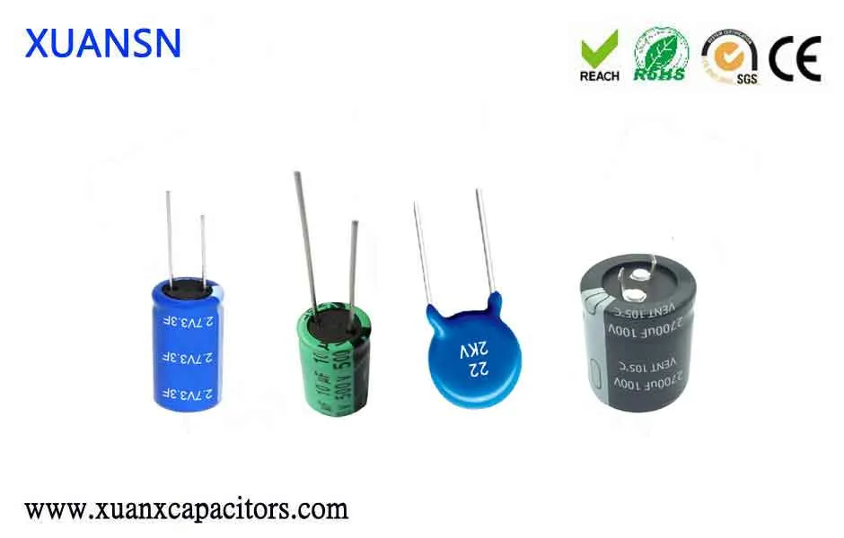
Check the voltage rating on the capacitor casing to ensure it exceeds your circuit’s peak voltage. Using a lower rating will often cause the electrolyte to vent or explode.
For circuits with AC ripple, add that ripple to the DC baseline before comparing against the rating. A 16V capacitor fed by 12V DC and 5V of ripple sees 17V peaks. It fails within hours.
Connect the positive lead to the higher potential side if you’re using a polarized electrolytic capacitor. Reversing polarity causes an internal short or permanent damage.
If your signal swings below ground, use a non-polarized film capacitor instead. Electrolytics can’t handle reverse bias even briefly without degrading the oxide layer.
Place a resistor in series with the capacitor to limit initial inrush current during charging. This prevents damage to your power supply when the circuit is energized.
Size this resistor based on your supply’s current limit. A 10-ohm resistor limits a 5V supply to half an amp. Remove it only after the capacitor reaches full charge.
Calculate capacitive reactance using Xc = 1 / (2 * π * f * C) to understand how much current flows at a given frequency. This technical guide from the University of Colorado explains the relationship between frequency and impedance in electronic circuits.
This formula assumes ideal behavior. Real capacitors carry parasitic inductance that dominates above their self-resonant frequency. Above that point, the component acts like an inductor.
Discharge the capacitor safely using a high-ohm resistor before touching any terminals. Never short the leads with a screwdriver. The sudden spark damages terminals or causes injury.
Time Constants and Circuit Response
The time it takes for a capacitor to charge or discharge depends on the resistance and capacitance values in the path. A larger resistance slows the process, while a larger capacitance stores more energy and requires more time to fill. Engineers define this duration using the time constant, tau (τ), calculated as the product of resistance in ohms and capacitance in farads.
A circuit reaches approximately 63% of its final voltage after one time constant. It takes five full time constants to reach 99% of the target voltage, which is the standard threshold for a steady state. If your circuit requires sub-millisecond response times, you must keep the product of resistance and capacitance below 0.0002 seconds.
| Situation | Time to Charge | What changes it | What to watch for |
|---|---|---|---|
| Low resistance | Very fast | Resistance value | High current spikes |
| High resistance | Very slow | Resistance value | Signal lag |
| High capacitance | Long duration | Farad rating | Power supply strain |
| Low capacitance | Short duration | Farad rating | Rapid voltage drops |
If the circuit takes significantly longer to reach a steady state than your calculations suggest, check for leakage current or a failing dielectric layer. These defects effectively add a parallel resistance path, forcing the capacitor to draw constant current that prevents it from ever reaching full potential.
Identifying Proper Operation
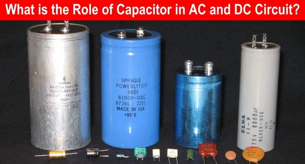
You can tell a capacitor is working correctly in a DC circuit by using a multimeter set to measure voltage. When you first connect the power, the voltage across the capacitor should rise gradually until it matches the source.
If the voltage remains at zero, the capacitor is likely open; if it jumps to the source value instantly, the capacitor may be shorted or the circuit path is incomplete. In an AC circuit, a functioning capacitor will show a measurable current flow when tested with an ammeter.
If you’re unsure about the state of a component, a capacitance meter provides the most accurate reading. You must disconnect the capacitor from the circuit completely before testing it with a meter. If the measured value differs by more than 20% from the label, the component has likely degraded and should be replaced. Always consult the manufacturer’s datasheet for the specific tolerance ranges allowed for your model.
Most beginners make the mistake of testing capacitors while they remain soldered to the board. This creates a parallel path for current, leading to false readings that suggest a healthy component when it’s actually failing. If your meter shows a value significantly higher than the label, you’re likely measuring other components in the circuit. Always isolate one leg of the capacitor to ensure an accurate result.
Common Operational Errors
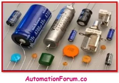
Placing a polarized capacitor backward in a DC circuit causes the internal electrolyte to boil and the chemical structure to break down. This error typically results in the component bulging, venting, or leaking, which permanently ruins the surrounding circuit board traces. Always check for the stripe or indentation marking the negative terminal before soldering.
Applying a voltage higher than the rated limit causes the dielectric material inside the capacitor to puncture. This leads to a catastrophic failure where the device loses all storage capability and becomes a dead short circuit. If your power supply fluctuates, choose a capacitor rated for at least 1.5 times the maximum expected voltage to build in a safety margin.
Attempting to use a polarized electrolytic capacitor in a high-frequency AC signal path causes excessive heat buildup due to high internal resistance. If the signal frequency exceeds 100 kHz, use non-polarized ceramic or film capacitors instead. These materials remain stable and cool, preventing the signal distortion that occurs when an electrolytic component begins to degrade under high-frequency stress.
Related guides
Frequently asked questions
Can I use a dc capacitor in an ac circuit?
No, you shouldn’t use a standard polarized dc capacitor in an ac circuit because the voltage reversal will cause the component to overheat and fail. If you must use a capacitor for ac, choose a non-polarized type such as a ceramic, film, or bipolar electrolytic model. These are designed to handle the continuous polarity shifts without the internal damage that occurs in polarized dc versions.
How long does a capacitor hold a charge?
A capacitor holds a charge for a duration that depends on its internal leakage resistance and the connected load. In an ideal environment, it can hold a charge for hours or even days, but in a real circuit, it usually discharges in seconds or minutes through the surrounding components. Always treat any capacitor as if it’s charged until you have measured it with a meter.
Is it safe to touch a capacitor after turning off power?
No, it isn’t safe to touch a capacitor immediately after power is removed because it can store a dangerous amount of energy. You must discharge the capacitor using a proper discharge tool or a resistor before you handle it. Never assume a device is safe just because it’s unplugged, as the stored energy can cause a painful electric shock or burn.
What happens if the capacitance value is too low?
If the capacitance value is too low for the application, the circuit will fail to filter the signal or store enough energy to perform its function. In a power supply, this results in significant ripple voltage, which creates noise and instability. You should always select a capacitance value that matches the requirements defined in your circuit design or schematic to ensure proper performance.
How do I identify if a capacitor is polarized?
You can identify a polarized capacitor by looking for a stripe or a minus sign on the side of the body, which indicates the negative terminal. Ceramic capacitors are typically non-polarized and have no markings indicating polarity, while electrolytic capacitors almost always have clear markings. If you see no markings, the component is likely non-polarized, but checking the datasheet for the specific part number is the safest method.
Conclusion
Understanding how these components behave is a great way to start building your own electronics projects. If you’re curious to see this in action, grab a small LED and a capacitor to experiment with a simple timing circuit. You’ll quickly see how they shape the flow of electricity in real time.
