
Ceramic capacitors are small electronic parts that store energy in an electric field between two conductive plates separated by a ceramic material. They’re used in almost every piece of modern electronics, from smartphones to power supplies, to filter signals and stabilize voltage. Because they have no polarity, they’re easy to install in a circuit without worrying about the direction of the connection.
These components function by using a dielectric made of ceramic, which allows them to be very small while still holding a charge. They’re perfect for high-frequency applications because they have low internal resistance. If you’re designing a high-power circuit, use a film capacitor; if you’re working on a small, high-frequency signal circuit, choose a ceramic capacitor.
The most common mistake people make is choosing a capacitor with a voltage rating that’s too low for their circuit. This often causes the component to short or burn out once it’s powered on. Always check your circuit’s maximum operating voltage and select a capacitor rated for at least twice that value to ensure it stays safe and reliable.
Handling and installing ceramic capacitors
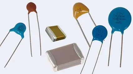
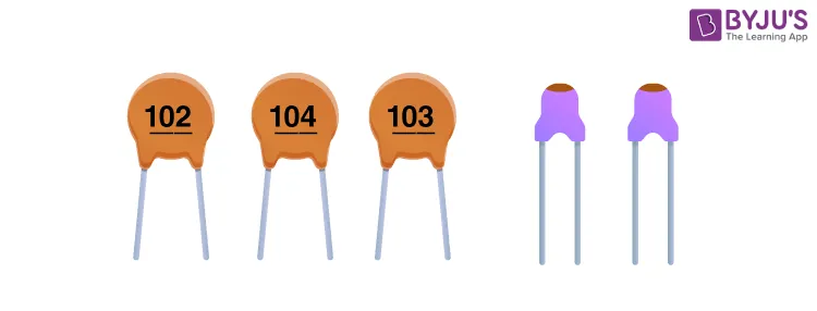
- Identify the capacitance value and voltage rating from the component’s packaging or datasheet. These numbers tell you how much energy it stores and the maximum pressure it can withstand.
- Check the circuit schematic to confirm the placement. You must place the capacitor as close to the power pins of your integrated circuit as possible to minimize noise.
- Solder the leads to the circuit board pads using a standard soldering iron set to 650°F (343°C). Don’t hold the iron on the leads for more than 3 seconds to avoid cracking the ceramic body from thermal shock.
- Clip the excess wire leads using flush cutters. Ensure the cuts are clean and that no metal scraps fall onto the board, as these can cause short circuits.
- Verify the connection by testing the board with a multimeter. If the board doesn’t function, check the solder joints for cold spots or bridges between pins.
Tip: If you’re soldering, use a small amount of flux to help the solder flow evenly. This prevents the need for excessive heat, which is the main cause of component failure.
Tip: Always wear safety glasses when clipping leads. The small metal wires can fly off at high speeds and cause eye injuries.
Measuring Time and Performance
The time it takes for these parts to work depends on the circuit design and the specific type of ceramic used. Standard class 1 capacitors, like the C0G type, are very stable over time. Class 2 types, like X7R, may change their capacitance based on the voltage applied to them. According to the International Electrotechnical Commission, these standards define how components must perform under specific environmental conditions.
| Type | Stability | Best Use | What changes it |
|---|---|---|---|
| C0G / NP0 | High | Precision timing | Minimal change across rated conditions |
| X7R | Medium | Filtering | Applied voltage |
| Y5V | Low | General bypass | Aging and heat |
A common mistake is assuming an X7R capacitor keeps its labeled value at full working voltage. At its rated voltage, a typical X7R part can lose half its stated capacitance. If your timing loop relies on that exact value, your pulse width will drift far past acceptable limits.
If your circuit isn’t performing as expected, check the datasheet for your specific model. Look for the DC bias curve rather than just the summary table. Capacitors often lose effectiveness if the operating temperature exceeds the range listed in their technical specifications.
Identifying Proper Operation
You can tell if a capacitor is working by checking the stability of the voltage in your circuit. If you have an oscilloscope, you should see a flat, clean line on the power rail. If you see a lot of “noise” or wavy lines, the capacitor might not be filtering the power correctly.
Physical signs of failure include cracks on the surface of the ceramic or a burnt smell. If the component looks discolored or has a small hole, it has failed and must be replaced. A multimeter set to the capacitance mode can confirm if the part still measures the correct capacitance value. If the reading is significantly lower than the label, the component is likely damaged.
Most beginners make the mistake of testing capacitors while they’re still soldered to the board. This often yields a false reading because other components interfere with the measurement. Always desolder at least one leg of the capacitor before testing it with a meter.
If you’re working with electrolytic capacitors, look for a bulging top or leaking electrolyte fluid. These are signs of internal pressure buildup. If the top is flat and the casing is firm, the device is likely healthy.
Avoiding Common Failures
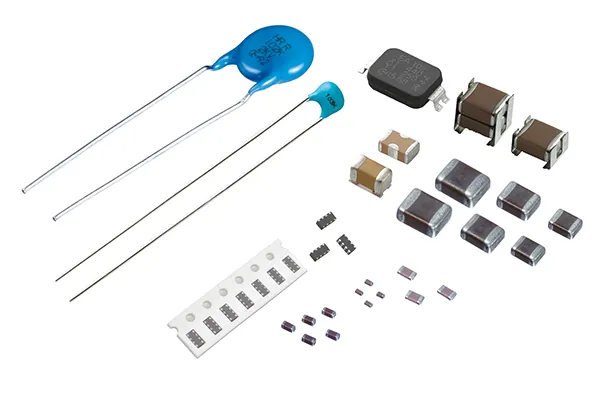
- Excessive Heat: Applying too much heat during soldering can crack the internal dielectric layers. Use a temperature-controlled iron and work quickly to protect the internal structure from thermal shock. Keep your tip below 300°C for standard multilayer ceramics. Handheld butane irons often exceed this limit without warning.
- Wrong Voltage Rating: Using a capacitor with a lower voltage rating than the circuit’s peak voltage leads to immediate failure. Always ensure the capacitor’s rating exceeds your circuit’s working voltage.
- Mechanical Stress: Ceramic is brittle and will crack if the circuit board is bent or dropped. Ensure the board is mounted securely in a case so it doesn’t flex during use. Never place large ceramic capacitors within 2mm of a mounting hole or board edge. Screws compress the fiberglass and propagate fractures straight through the component body.
Frequently asked questions
How long do ceramic capacitors last?
They can last for a long time when operated within their specified voltage and temperature limits. Because they have no liquid electrolyte, they don’t dry out like aluminum electrolytic capacitors. If you keep them in a cool, dry environment and don’t exceed their rated voltage, they will likely outlive the device they’re installed in.
Is it safe to touch ceramic capacitors?
Yes, it’s generally safe to touch them, but you should never touch a capacitor that’s part of a high-voltage circuit while the power is on. Even after the power is turned off, some capacitors can hold a dangerous electrical charge for a short time. If you’re unsure, use a multimeter to verify that the voltage across the terminals is zero before touching anything.
Why do ceramic capacitors fail?
They usually fail because of physical cracks or voltage spikes that exceed their rated limits. A crack in the ceramic can cause an internal short circuit, which may lead to the part heating up or failing entirely. You can prevent this by handling boards carefully and ensuring your power supply is regulated to stay within the safe operating range of your components.
Can I replace a ceramic capacitor with another type?
You can, but it depends on the requirements of your specific circuit. If the original was a ceramic type used for high-frequency filtering, replacing it with a large, slow electrolytic capacitor will likely cause your circuit to stop working correctly. Always try to match the capacitance value and the frequency characteristics of the original part if you need to make a substitution.
How do I know which ceramic capacitor to buy?
You should prioritize the capacitance value, voltage rating, and dielectric code. The dielectric code indicates how stable the component remains during temperature fluctuations. For general hobby projects, X7R capacitors offer a reliable balance of stability and performance where extreme precision isn’t required.
Conclusion
Selecting the right component is essential for your project’s success, so you shouldn’t hesitate to check the datasheet before soldering. You’ll find that understanding these reliable parts makes designing circuits much simpler. Once you’ve picked the correct values for your build, you’re ready to start experimenting with your own custom electronics.
