
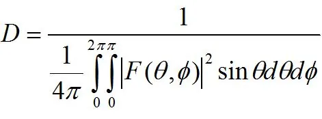
Antenna directivity is the ability of an antenna to focus radio waves in a specific direction rather than radiating power equally in all directions. It’s measured by comparing the maximum radiation intensity of the antenna to the intensity of an ideal isotropic radiator, which spreads energy uniformly in a sphere. This ratio is usually expressed in decibels, or dBi, to quantify the gain.
How antenna directivity is measured
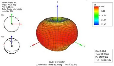
When you evaluate how well an antenna concentrates energy, you look at its radiation pattern. This pattern shows how the signal strength changes as you move around the antenna in 3D space.
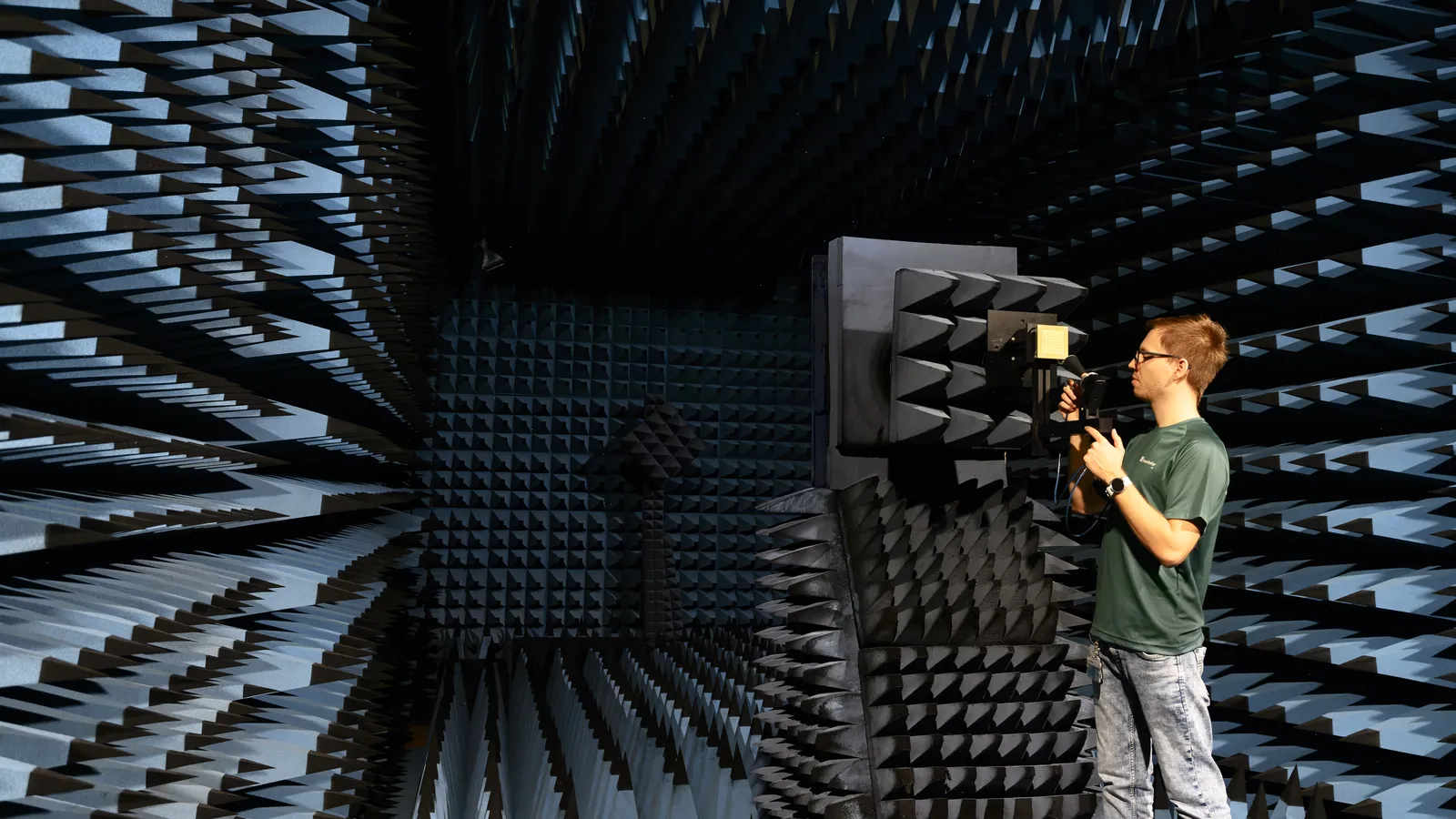
Measure the radiation intensity at the peak point of the signal lobe. Compare this peak value to an isotropic source that radiates equally in all directions. Calculate the ratio in decibels to find the directivity value. Use an anechoic chamber to prevent signal reflections from changing your test data. Rotate the antenna on a turntable to map the signal strength at every angle.
If your test environment includes walls or metal objects, you’ll record multipath interference. This noise creates “ghost” lobes that don’t exist in the real world. To avoid this, ensure your test distance exceeds the Fraunhofer distance, calculated as two times the square of the antenna’s largest dimension divided by the signal wavelength. If you can’t reach this distance, your gain readings will be inaccurate.
Why Signal Focus Matters
The focus of an antenna happens because the physical design restricts or guides the flow of radio frequency energy. By shaping the metallic elements or the reflective surface, you force the electromagnetic waves to travel in a preferred path. This process effectively increases the signal strength in the target direction without needing to add more electrical power to the system.
If you have a high-directivity antenna, you get a much stronger signal at the receiver end compared to a simple omnidirectional antenna. This is why satellite dishes are shaped like bowls; the curved surface catches signals from a wide area and reflects them into a single, highly focused point.
This mechanism relies on the conservation of energy. Since the total power sent to the antenna remains constant, concentrating that power into a narrow beam naturally makes it stronger in that specific line of sight. If you focus the energy into a narrower beam, the gain increases, but the coverage area shrinks. If you spread the energy wider, the gain drops, but you can reach more devices over a larger physical territory.
You can determine your needs by measuring the beamwidth in degrees. A narrow beam under 30 degrees requires precise alignment, often needing a physical mount to prevent wind sway from dropping the connection.
If you’re mounting in an area with high vibration or shifting obstacles, stick to a wider beam of 60 degrees or more. The mistake most users make is choosing the highest gain antenna available, which often creates a signal so narrow that even minor structural settling causes a complete network outage.
When Directivity Varies
The measurement of directivity changes based on the environment and the frequency you use. A design that works well at one frequency often performs differently when you change the operating band.
When the wavelength shrinks at higher frequencies, the effective aperture of your antenna narrows. If you fail to scale your elements down, you’ll experience side-lobe leakage that degrades signal integrity.
Metal surfaces introduce multipath interference that masks your true directivity. If you can’t move the antenna to open space, you must employ directional shielding to force a clean radiation pattern.
You should monitor the beam width closely. When the beam narrows, even a two-degree misalignment causes a significant drop in signal strength. If your gain values fluctuate unexpectedly, check the beam pattern for unintended nulls.
If you encounter obstacles, don’t simply increase power. Raising the antenna height by just three wavelengths often resolves the blockage. This approach preserves your directivity while avoiding the noise floor issues caused by excessive transmission power.
Proper Testing Procedures
Mount your antenna on a non-conductive stand at least two meters above the ground to avoid ground-plane interference that skews your radiation pattern.
Place your reference antenna at a distance that meets or exceeds the Fraunhofer distance from the test unit. This ensures you’re measuring in the far-field region where the wave front is planar. If you test in the near-field, your gain calculations will be artificially inflated by reactive energy.
Transmit a continuous wave signal while rotating the antenna in five-degree increments. Capture data for both horizontal and vertical polarizations to build a complete 3D radiation sphere.
Identify the peak power value across all recorded angles to determine maximum intensity. Divide this peak by the reference power of a theoretical isotropic source, then convert the result to decibels to find the absolute gain.
If your gain value fluctuates by more than 0.5 decibels between consecutive tests, check your cable shielding. Loose connectors often introduce noise that mimics high-gain performance.
Common Mistakes That Ruin Results
Testing too close to the antenna captures the reactive near-field rather than the intended far-field radiation. To avoid this, ensure your distance exceeds the Fraunhofer distance, calculated as 2D²/λ where D is the antenna diameter and λ is the wavelength. Measuring inside this boundary renders your gain data effectively useless.
Reflective surfaces near your setup create multipath interference. If you can’t move to an anechoic chamber, cover concrete floors or metal walls with microwave-absorbent foam. Without this shielding, you’ll see phantom lobes in your radiation pattern that don’t exist in reality.
Failing to calibrate your vector network analyzer before every session introduces drift. If your baseline shifts by even 0.5 dB, your directivity measurements will fail verification. Always perform a full SOLT calibration at the cable ends. This simple step prevents systematic errors that invalidate your entire data set.
Related guides
Frequently asked questions
Can directivity be measured without a chamber?
It’s possible to measure directivity outdoors in an open field, but you must ensure there are no nearby buildings or trees. These objects reflect radio waves and distort the radiation pattern, which makes your measurements unreliable. If you can’t find a perfectly clear space, the test results won’t match the true performance of the antenna.
How long does a test take?
A full 3D measurement typically takes 30 to 60 minutes, depending on the rotation speed of your turntable. You must pause at each measurement interval to let the signal stabilize before recording the power level. If you only need a 2D pattern, you can finish the test in about 15 minutes by rotating the antenna in one plane.
Does directivity change with cable length?
Directivity itself is a property of the antenna design and doesn’t change based on cable length, but your measured gain will drop if the cable is too long. Longer cables introduce signal attenuation, which absorbs some of the power before it reaches the antenna. Always use the shortest possible cable to keep your signal strength as high as possible.
Is high directivity always better?
High directivity is better for point-to-point communication, but it’s a disadvantage if you need to cover a wide area. If you use a high-gain antenna, you must aim it perfectly at the receiver, or you’ll lose the connection entirely. Choose a low-directivity antenna if you need to serve multiple devices spread out in different directions.
What happens if I misalign the antenna?
Misalignment causes a significant drop in signal strength because the beam is pointed away from the intended target. If your antenna has high directivity, even a shift of a few degrees can reduce the signal by several decibels. Always use a signal meter to verify your alignment until you reach the strongest possible reading at the receiver.
Does frequency affect the measurement?
Frequency is the most important factor, as the physical size of the antenna must match the wavelength of the signal. If you change the frequency, the radiation pattern will shift, and your directivity value will no longer be accurate. You must repeat the measurement process every time you change the operating band of your radio equipment.
Conclusion
The directivity you achieve is limited by the physical size of the antenna in relation to the wavelength of the signal you’re using. A larger antenna surface allows for tighter beam control, while a smaller antenna is naturally forced to radiate in a wider pattern. Always consult the manufacturer’s technical data sheet to see the specific directivity range for your model.
