
Additive manufacturing works by translating a three-dimensional digital model into a series of thin, physical cross-sections that a machine builds layer by layer until the final object is complete. This process transforms abstract geometry into tangible parts through a sequence of software preparation, material deposition, and post-processing stages. By reading a virtual file, the machine orchestrates the precise placement of polymers, metals, or composites to solidify shapes that would be impossible to create using traditional subtractive methods like milling or turning.
Key Takeaways
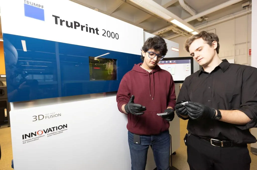
- Always ensure your 3D model is “watertight” or manifold to prevent structural gaps or printing errors.
- Orientation of the part on the build plate significantly impacts both the surface finish and the required support structures.
- Choose your material based on the mechanical requirements, such as tensile strength, thermal resistance, or chemical compatibility.
- Post-processing, including cleaning and curing, is often as important as the printing phase for final part integrity.
- Regular machine calibration is essential for maintaining dimensional accuracy across complex geometries.
How Additive Technologies Work From File To Object
The journey from a digital concept to a physical object is a structured pipeline that bridges computer-aided design and mechanical execution. The process begins with a 3D model, typically generated in software like Autodesk Fusion 360 or SolidWorks.
This model must be exported as a standard format, most commonly an STL file, which approximates the surface geometry using a mesh of triangles. Once the file is exported, it enters the slicer software, which acts as the translator between your design and the printer’s hardware.
The slicer divides the model into hundreds or thousands of horizontal layers. During this stage, you define specific parameters such as layer height, infill density, and support structures. The slicer then generates G-code, a programming language that instructs the printer on exactly where to move, how much material to extrude, and the temperature at which to operate. This G-code is the final instruction set that the machine interprets to physically construct the object.
The Role of Slicing Software
Slicing software is the most critical bridge in the additive manufacturing workflow. Without a properly configured slicer, even the most expensive printer will fail to produce an accurate part. The software allows you to visualize how the internal structure will look, ensuring that the part has sufficient strength where needed while saving material in non-critical areas.
| Parameter | Function | Impact on Part |
|---|---|---|
| Layer Height | Determines thickness of each slice | Affects resolution and print time |
| Infill Density | Internal geometric support | Dictates weight and part strength |
| Shell Count | Number of outer wall passes | Improves durability and finish |
| Support Type | Temporary scaffold for overhangs | Prevents sagging on complex shapes |
Material Deposition and Curing Methods
Depending on the technology, the machine builds the object using distinct physical principles. Fused Deposition Modeling (FDM) melts thermoplastic filament through a heated nozzle. Stereolithography (SLA) uses a laser to cure liquid photopolymer resin into a solid. Selective Laser Sintering (SLS) uses a high-power laser to fuse powdered material, typically nylon, into a dense, structural part. Each method requires different handling of materials and environmental controls.
Material selection remains the most significant variable in determining the success of a print. For instance, using PLA for high-heat environments will lead to deformation, whereas using PETG provides better thermal stability. Professionals often consult technical data sheets to ensure the material properties align with the intended use case, as documented in the ASTM International F2792 additive manufacturing terminology standards guide.
Managing Complex Geometric Overhangs
One of the most common challenges in additive manufacturing is printing overhangs or bridges where there’s no material beneath the current layer. If a printer attempts to deposit material into thin air, the molten plastic will droop or fail to adhere. Support structures serve as temporary scaffolds that are removed after the print is complete.
- Tree-style supports for complex, organic shapes.
- Grid-style supports for standard, blocky geometries.
- Breakaway supports for easy manual removal.
- Dissolvable supports for intricate internal channels.
Pro Tip: When designing for additive manufacturing, try to incorporate chamfers or fillets at 45-degree angles to minimize the need for support structures, which reduces material waste and finishing time.
Critical Post-Processing Workflow Steps
Once the machine finishes the build, the object is rarely ready for immediate use. Post-processing is the final step that refines the part. For FDM prints, this involves snapping off supports and sanding surfaces. For resin-based technologies, the part must be washed in isopropyl alcohol to remove excess liquid resin and then cured under UV light to finalize the chemical cross-linking of the polymers.
| Technology | Cleaning Method | Final Curing Step |
|---|---|---|
| FDM | Mechanical support removal | None required |
| SLA | Isopropyl alcohol bath | UV light chamber |
| SLS | Compressed air cleaning | Heat stabilization |
Is Calibration Necessary Every Time?
While you don’t need to recalibrate your printer before every single print, you must perform periodic checks. Over time, belts can stretch, build plates can shift, and nozzles can clog. A machine that’s out of calibration will produce layers that don’t align, leading to “layer shifting” or poor surface adhesion. Routine maintenance ensures that the G-code instructions result in the expected physical outcome every time.
Warning: Never attempt to clear a clogged nozzle while it’s hot without wearing proper heat-resistant gloves, as the heating block can reach temperatures exceeding 250 degrees Celsius, posing a significant burn risk.
Selecting the Right Printer Type

Choosing the correct hardware depends on your specific goals. Hobbyist-grade FDM printers are excellent for prototyping and functional parts that don’t require high aesthetic detail. Industrial SLA machines are preferred for high-precision models, such as dental molds or jewelry casts, where surface finish is paramount.
- Prusa Research (FDM)
- Formlabs (SLA)
- Stratasys (Industrial-grade FDM/PolyJet)
- UltiMaker (Professional FDM)
Frequently Asked Questions
Can I print any shape I design?
While additive manufacturing allows for extreme geometric freedom, you’re still limited by the machine’s physical constraints. Very thin walls might collapse, and extreme overhangs require support. You must design with the printer’s specific capabilities in mind to ensure the physical object maintains its integrity during the build process.
How do I fix a failed print?
A failed print usually results from poor bed adhesion, improper temperature settings, or a corrupted G-code file. Check your first layer height to ensure the nozzle is close enough to the build plate. If the part detaches mid-print, increase your bed temperature or use an adhesive agent like glue sticks or specialized build surfaces to improve grip.
What is the purpose of infill?
Infill is the internal structure printed inside the walls of your object. Instead of printing a solid, heavy, and expensive block of material, the printer creates a honeycomb or grid pattern. This provides the necessary structural support to keep the part from crushing under pressure while keeping the overall material volume and print time manageable.
How long does the process take?
Print duration depends on the volume of the part, the layer height, and the print speed. Small objects might take thirty minutes, while large, high-detail prints can take several days. Increasing the layer height speeds up the process but reduces the surface quality, whereas lower layer heights produce smoother results but require significantly more time to complete the build.
Are all 3D printed parts waterproof?
Not necessarily. FDM prints, in particular, are often porous because they’re built from layers of extruded plastic that may not fuse perfectly. If you need a waterproof part, you must increase the wall count (perimeters) and perhaps apply a sealant or epoxy coating to the exterior to fill any microscopic gaps between the printed layers.
Conclusion
Understanding the transition from a digital file to a physical object is about mastering the interplay between your design software and the printer’s mechanical limits. By focusing on proper file preparation, choosing the right material, and executing careful post-processing, you can produce high-quality parts consistently. Your next step is to download a test model and run it through your chosen slicer software to observe how it interprets your geometry.
