
Third angle projection works by placing the object inside a transparent glass box where the views are projected onto the sides of the box closest to the observer. In this system, the “view” is captured by looking through the object toward the plane of projection, meaning the top view is placed above the front view, and the right-side view is placed to the right of the front view. This arrangement creates a logical, intuitive flow that mirrors how we physically perceive an object when walking around it. Because the observer sees the object between themselves and the projected plane, the resulting drawing represents the physical reality of the part from the specific angle of the viewer.
Key Takeaways
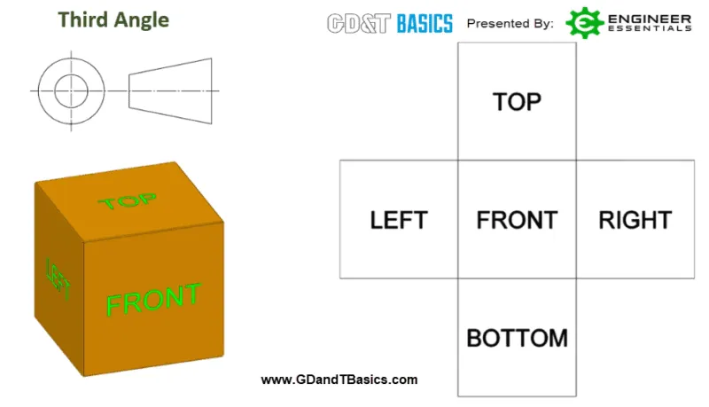
- Always place the top view directly above the front view to maintain alignment.
- Use the right-side view by positioning it to the right of the front view.
- Identify the projection system by looking for the specific symbol on the title block.
- Keep the orthographic views aligned horizontally and vertically to ensure precision.
- Remember that third angle is the standard in the United States and Canada.
How Third Angle Projection Works
The core concept relies on the principle of placing the observer, the projection plane, and the object in a specific sequence. Unlike first angle projection, where the object sits between the observer and the plane, the third angle method places the projection plane between the observer and the object. Imagine a clear plastic box enclosing a mechanical component.
As you look through the front face of the box, you draw what you see onto that face. Because you’re looking through the glass at the object, the image captured is exactly what your eye perceives from that specific vantage point. This makes the drawing process highly intuitive for engineers and machinists who need to visualize the final part.
The Role of Projection Planes
In this system, there are six potential planes: front, top, bottom, left, right, and rear. In practice, most technical drawings only require three views—front, top, and right—to fully define the geometry of a part. Each plane acts as a mirror that captures the silhouette and internal features of the object. By flattening these six planes into a two-dimensional sheet, the technical drawing standard creates a standardized map that anyone trained in the system can interpret without ambiguity.
| View Position | Relationship to Front View | Purpose |
|---|---|---|
| Top View | Placed directly above | Shows width and depth |
| Front View | Primary reference point | Shows height and width |
| Right View | Placed to the right | Shows height and depth |
| Bottom View | Placed below front | Shows underside details |
Why Use This Projection System?
The primary benefit of third angle projection is its direct correlation to the physical part. When a machinist looks at a drawing, they expect the right side of the object to appear on the right side of the paper. This reduces the cognitive load required to interpret the engineering prints, leading to fewer manufacturing errors.
By adhering to the guidelines set by the American Society of Mechanical Engineers, companies ensure that their technical documentation remains consistent across international supply chains. This consistency is vital for modern manufacturing where components might be designed in one country and produced in another.
Identifying the Projection Symbol
You can always tell which system a drawing uses by checking the title block for the projection symbol. The third angle symbol features a truncated cone shown in two parts: a small circle on the left and a larger circle on the right, representing the view of the cone from the side.
If you see this symbol, you know immediately that the top view is above the front view. Failing to check this symbol is a common mistake that leads to “flipped” parts, which can be an expensive error in high-precision industries like aerospace or medical device manufacturing.
Essential Layout Guidelines
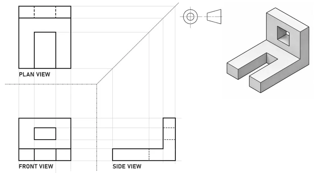
To produce a professional technical drawing, you must follow strict layout rules. These rules ensure that the multi-view drawing remains readable regardless of the complexity of the part.
- Vertical Alignment: The top, front, and bottom views must share the same vertical centerline.
- Horizontal Alignment: The left, front, and right views must share the same horizontal centerline.
- Spacing: Maintain consistent gaps between views to allow for dimensioning without cluttering the drawing.
- Scale: All views must be drawn at the same scale unless specifically noted otherwise.
Pro Tip: Use a light construction line, often called a miter line at a 45-degree angle, to project depth dimensions from the top view to the side view, ensuring that your depth measurements are perfectly consistent across the page.
Comparing Projection Methods
Understanding how third angle differs from first angle is critical for students and professionals. While both use the same principles of orthographic projection, the placement of the views relative to the object is inverted.
| Feature | Third Angle Projection | First Angle Projection |
|---|---|---|
| Primary Region | USA, Canada, Australia | Europe, Asia, South America |
| View Orientation | Logical, intuitive | Inverse, counter-intuitive |
| Symbol | Cone on the left | Cone on the right |
| Standard | ANSI/ASME | ISO |
Common Drafting Mistakes
Even experienced drafters sometimes fall into bad habits. One of the most frequent errors is failing to maintain the alignment of views. If your views are shifted even slightly, the drawing becomes difficult to read, and dimensions may be misinterpreted. Another common issue is missing hidden lines.
In third angle, all hidden features must be represented with dashed lines, regardless of which view is being considered. If you’re drawing a hole that’s visible from the top but not the front, it must be represented as a dashed line in the front view.
Warning: Never mix projection methods on a single drawing sheet; if you start in third angle, every view and detail must remain in that system to avoid catastrophic misinterpretation of the geometry.
Tools for Creating Projections
Drafting is now almost exclusively performed using CAD software, but the principles remain the same. Whether you use legacy drafting boards or modern software, the geometric accuracy is the most important factor.
- AutoCAD: The industry standard for 2D drafting and layout.
- SolidWorks: Excellent for generating automated 2D views from 3D models.
- Drafting Board: Necessary for learning the manual principles of projection.
- Drafting Templates: Helpful for drawing standard circles and fillets quickly.
Troubleshooting Your Drawings
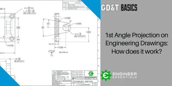
If you find that your views don’t align, start by checking your construction lines. Often, a simple error in the initial projection from the front view propagates through the entire drawing. If you’re using CAD, check your software settings to ensure the projection type is set to “Third Angle” in the sheet properties.
Many programs default to the system based on the template region, so always verify this before you begin placing your views. If dimensions look wrong, recalculate the depth using the miter line method to verify that your top view and right side view match perfectly.
Related guides
- Straight Stop Valve vs Angle Stop Valve: How to Choose in 2026
- Best Angle Stop Valves: Why Brass Ball Valves Are Superior in 2026
Frequently Asked Questions
Is third angle projection the global standard?
No, it’s primarily the standard in the United States and Canada. Most of the rest of the world, including Europe and many parts of Asia, utilizes the first angle projection system. While both are mathematically valid, the geographic divide in usage means you must always check the projection symbol on any technical drawing before you begin manufacturing or interpretation.
Can I convert a drawing from first to third angle?
Yes, you can convert a drawing, but it requires rearranging the views entirely. You must move the top view to the opposite side of the front view and flip the side views as well. This is a manual process that requires careful attention to detail. It’s usually more efficient to regenerate the views from the original 3D model if one is available.
Why do my dimensions look wrong?
Dimensions often look wrong because the views aren’t properly aligned. In third angle projection, the width of the top view must match the width of the front view exactly. If they don’t align, your projection is incorrect. Always use construction lines to project points between views to ensure that the geometry remains consistent across the entire sheet, preventing errors in the shop.
Does the projection system affect the 3D model?
No, the projection system only affects how the 2D views are laid out on a flat sheet of paper. The 3D model itself is independent of the projection system. You can generate either first or third angle views from the exact same 3D CAD model by simply changing the settings in your drawing template or sheet properties before you place the views.
Are hidden lines required in every view?
Yes, you must include hidden lines in every view where a feature exists but isn’t visible from that angle. This is a fundamental rule of technical drawing. Failing to include these lines makes it impossible to fully understand the internal geometry of a part, which can lead to significant manufacturing errors when a machinist tries to create the part from your drawing.
Conclusion
Mastering this system is a foundational skill for anyone working in engineering, architecture, or manufacturing. By consistently applying these rules, you ensure that your designs are clear, accurate, and professional. To improve your proficiency, try redrawing a simple household object using these projection principles on graph paper to practice your spatial visualization skills.
