
Mechanical cams offer precise motion control by turning rotating input into linear or oscillating output, which is the main reason they remain vital in industrial automation. While these devices provide high repeatability for complex tasks, they can suffer from wear over time if the surface contact isn’t maintained correctly.
Comparing mechanical cams with alternative motion systems
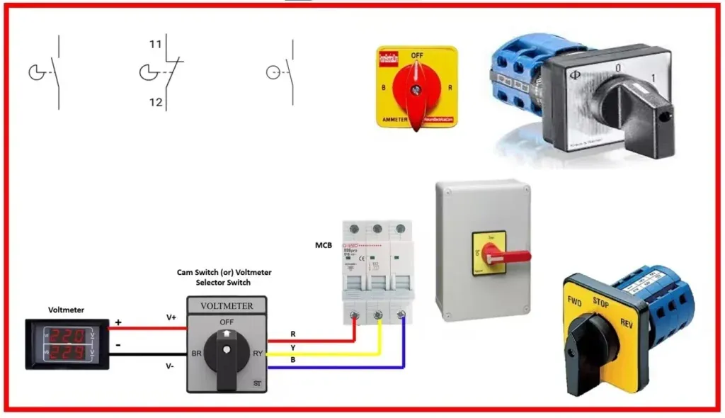
Choosing the right motion control method depends on your specific speed, precision, and load requirements. While mechanical cams provide excellent timing, other systems may offer more flexibility or lower maintenance costs depending on the application.
| Method | How long | Effort | Cost | Best for |
|---|---|---|---|---|
| Mechanical Cam | High | High | High | Fixed cycle speed |
| Servo Motor | Low | Low | Medium | Changing patterns |
| Pneumatic | Medium | Medium | Low | Simple movements |
| Hydraulic | Medium | High | High | Heavy lifting |
Mechanical systems provide reliable, high-speed movement without needing complex software. If your machine runs the same pattern for years, a cam is usually the most efficient choice. If you change your production line once a week, a programmable servo system is better.
Using plate cams for motion
Plate cams are the most common type for simple, flat-plane movements. They use a rotating plate with a shaped edge to move a follower back and forth.
Design the cam profile to match your required displacement curve. Use a pressure angle below 30 degrees to avoid jamming the follower against the housing.
Cut the profile from hardened steel to prevent premature surface degradation.
Attach the cam to the drive shaft using a keyed hub. Friction fits will slip under load, causing the timing of your machine to drift.
Adjust the follower spring tension to ensure constant contact during high-speed operation. If the follower bounces, the resulting impact will pit the steel edge.
These cams are excellent for high-speed, repetitive tasks where timing is critical. However, they’re rigid; if you need to alter the motion profile, you must manufacture an entirely new cam disk.
Benefits of cylindrical cams

Cylindrical cams feature a groove cut into the surface of a cylinder. This design allows for more complex, three-dimensional motion compared to flat plates, enabling the follower to move along the axis of rotation rather than just radially.
Calculate the groove path to ensure the follower transition remains smooth. If your pressure angle exceeds 30 degrees, the follower will likely bind; in this case, increase the cylinder diameter to reduce the slope.
Machine the groove with a CNC mill to hold tight tolerances. Anything looser introduces backlash, which destroys precision during high-speed reversals.
Install the follower pin into the groove, ensuring it fits with minimal clearance. Lubricate the groove regularly to reduce friction and heat buildup.
Cylindrical designs handle heavy loads better than plate cams because the follower is captured within the groove. The main weakness is the difficulty of cleaning the internal track, which can collect debris and cause the mechanism to bind.
Benefits of globoidal cams
Globoidal cams, also known as cone-drive cams, provide high torque and accuracy in a compact package. They’re often used in indexing tables where precise positioning is required.
The rollers engage the cam along two opposite flanks at once. This dual contact is what eliminates backlash entirely.
If your indexer must hold position while a tool presses against it, you need this geometry. A standard barrel cam will deflect under that same side load.
- Mount the cam on the input shaft, ensuring perfect alignment with the output indexer.
- Set the input speed to match the cycle time required for the indexing motion.
- Verify the contact pattern between the cam ribs and the indexer rollers.
- Monitor the gear mesh for any signs of vibration or excessive noise.
These systems offer zero-backlash performance, making them ideal for high-precision assembly lines. The primary drawback is their high manufacturing cost and the specialized knowledge needed to align them during installation.
Misalignment here doesn’t just cause noise. It concentrates force on one edge of the roller until the surface spalls.
Choosing the right motion system
Deciding which method to use depends on your production goals and resource availability. Each situation requires a different balance of flexibility and speed.
- When you’re in a hurry: Choose pneumatic actuators. They’re easy to install, require minimal setup time, and work well for simple, fast, point-to-point movements.
- When you’re doing this for the first time: Use servo motors. They allow you to correct mistakes through software changes rather than having to machine new metal parts.
- When you want the best possible result: Select mechanical cams. Nothing beats the raw, synchronized speed and repeatability of a well-designed cam system for long-term, high-volume production.
The trade-off is always between the immediate ease of software-based systems and the long-term reliability of mechanical hardware. If you choose a mechanical path, you trade the ability to change quickly for the ability to run forever.
Rules for all cam systems
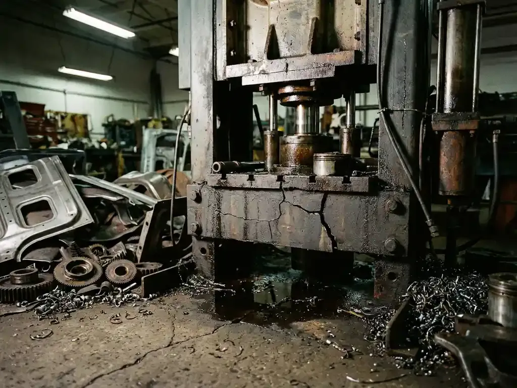
Regardless of the cam type you choose, certain universal standards apply to keep your equipment running safely. You must always maintain proper lubrication to prevent the metal from heating up and deforming.
Use the exact oil grade specified for your operating temperature range. A grease rated for low-speed conveyors will shear thin and fail inside a high-RPM packaging machine.
If your system runs at high speeds, check for signs of vibration or unusual noise every 500 hours of operation. Place a dial indicator on the follower rod during these checks.
Never attempt to modify a cam profile by hand; this usually creates uneven wear that destroys the follower. Even a slight change in the rise curve multiplies peak acceleration forces on the rest of the drivetrain.
If you don’t have the equipment to measure cam precision, consult a professional machine shop. Operating a mechanical system that’s out of balance carries a risk of catastrophic failure, so always follow the manufacturer’s maintenance schedule.
Frequently asked questions
Can I repair a worn cam?
No, you can’t effectively repair a worn cam profile by welding or filling it. Once the hardened surface is damaged, the cam will continue to wear rapidly; replacing the entire component is the only way to restore accuracy and safety.
How long do mechanical cams last?
Mechanical cams often last for millions of cycles if they’re properly lubricated and kept free of contaminants. The exact lifespan varies based on the load, the hardness of the material, and the speed of the machine, so check the manufacturer’s fatigue rating for your specific unit.
Is it safe to run a cam without a spring?
No, it isn’t safe to run most cam systems without a return spring or a captured groove. Without a force to keep the follower against the cam, the follower will lose contact at high speeds and cause dangerous impact forces that can break your machine.
What happens if the cam speed is too high?
If the cam speed exceeds the design limit, the follower will bounce and lose contact with the profile. This causes massive vibration, rapid surface pitting, and eventual failure of the cam and the follower assembly.
How often should I check the lubrication?
You should check the lubrication levels every 100 to 200 hours of operation, depending on the environment. If the machine operates in a dusty or hot area, you must check the oil or grease more often to prevent abrasive wear on the cam surface.
Why does my cam make a clicking sound?
A clicking sound usually means the follower is loose or the cam surface has developed a flat spot. This is a sign of imminent failure, and you should stop the machine immediately to inspect the contact surfaces for chips or cracks.
Conclusion
Choosing the right motion control setup doesn’t have to feel overwhelming. If you’re planning a new machine build, start by mapping out your exact speed and load needs before picking parts. That simple step will save you time, money, and unnecessary headaches later on.
