
An electrolytic capacitor stores energy using a thin oxide layer on a metal anode, typically aluminum or tantalum, and delivers high capacitance in a small package. These polarized components are built for filtering, smoothing and bulk storage in power supplies. They range from about 0.1 µF to over 1 F, handle voltages from 4 V to over 500 V, and wear out faster than ceramic types because their liquid or gel electrolyte dries over time.
The one thing that decides whether this part works or fails is polarity. You must connect the positive lead to the higher voltage side and the negative lead to ground or the lower potential. Reverse even a few volts and the oxide layer breaks down, generating gas inside the sealed can.
Connecting them backwards is the error that ruins boards. The capacitor heats up, swells, and eventually vents its electrolyte through the scored top or bursts entirely. That costs you the component, often damages nearby traces, and can injure anyone standing close when it pops.
How to choose and install them
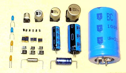
Picking the right part means matching four numbers to your circuit: capacitance, voltage rating, temperature limit and physical size. Once those match, installation is straightforward but demands attention to orientation and heat.
- Read the required capacitance in microfarads (µF) and the working voltage from your schematic or the old part’s label. Pick a replacement rated at least 20% above the circuit’s maximum voltage; for a 12 V rail, use a 16 V or 25 V part.
- Check the temperature rating printed on the sleeve. Use 105°C parts for switching power supplies or anything near hot components; 85°C types only work in cool, low-power signal paths.
- Match the lead spacing and diameter to the holes on your board. If the new part is wider, it won’t fit the footprint, and forcing it bends the leads until they crack.
-
Identify the negative stripe on the capacitor’s sleeve and the corresponding shaded pad or minus sign on the circuit board. Insert the leads so these marks align perfectly. Tip: A reversed aluminum capacitor might not fail immediately at low voltage, but it leaks current and degrades within hours. Always double-check the stripe before soldering.
-
Solder each lead quickly, keeping the iron on the joint for no more than 3 seconds per pin. Excess heat travels down the wire and boils the internal electrolyte, shortening the part’s life before the circuit ever turns on.
- Clip the excess lead flush with the bottom of the solder joint using diagonal cutters. Leave enough solder to form a small volcano shape around the wire.
- Clean the flux residue with isopropyl alcohol if the board runs sensitive analog signals. Leftover flux attracts moisture and creates tiny leakage paths across the pads.
If you’re replacing surface-mount versions on a dense motherboard, you’ll need a hot-air rework station set around 300°C and practice handling molten solder paste. Attempting this with a hand iron lifts the copper pads off the fiberglass, which requires professional board repair.
Time needed to replace an electrolytic capacitor
Swapping a through-hole part takes very little time once the board is out of its case. The actual soldering is fast, but getting access to the component usually dominates the clock. Here’s how long the job takes based on where the part lives.
| Situation | How long | What changes it | What to watch for |
|---|---|---|---|
| Open PCB, through-hole | 3–5 minutes | Your soldering speed | Burning the pad by holding the iron too long |
| Inside a desktop power supply | 15–30 minutes | Screws, plastic shields, tight cables | Forgetting to discharge the big filter caps first |
| Surface-mount on a logic board | 10–20 minutes | Hot-air tool warm-up, flux drying | Blowing tiny neighboring parts off their pads |
| Audio amplifier chassis | 20–45 minutes | Heavy brackets, glued wires, deep mounting | Stripping screws hidden under rubber feet |
These times assume you already have the correct replacement part sitting on your desk. Waiting for shipping adds days, and guessing at a value wastes the whole afternoon. If the removal drags past twice the upper limit shown here, stop applying heat. Put the iron down and check whether you missed a hidden screw or a grounding strap holding the board in place.
Signs an electrolytic capacitor has failed
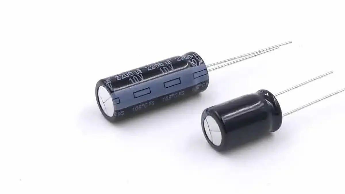
You don’t need expensive gear to spot a bad part. Visual clues come first, and they’re usually obvious once you know where to look.
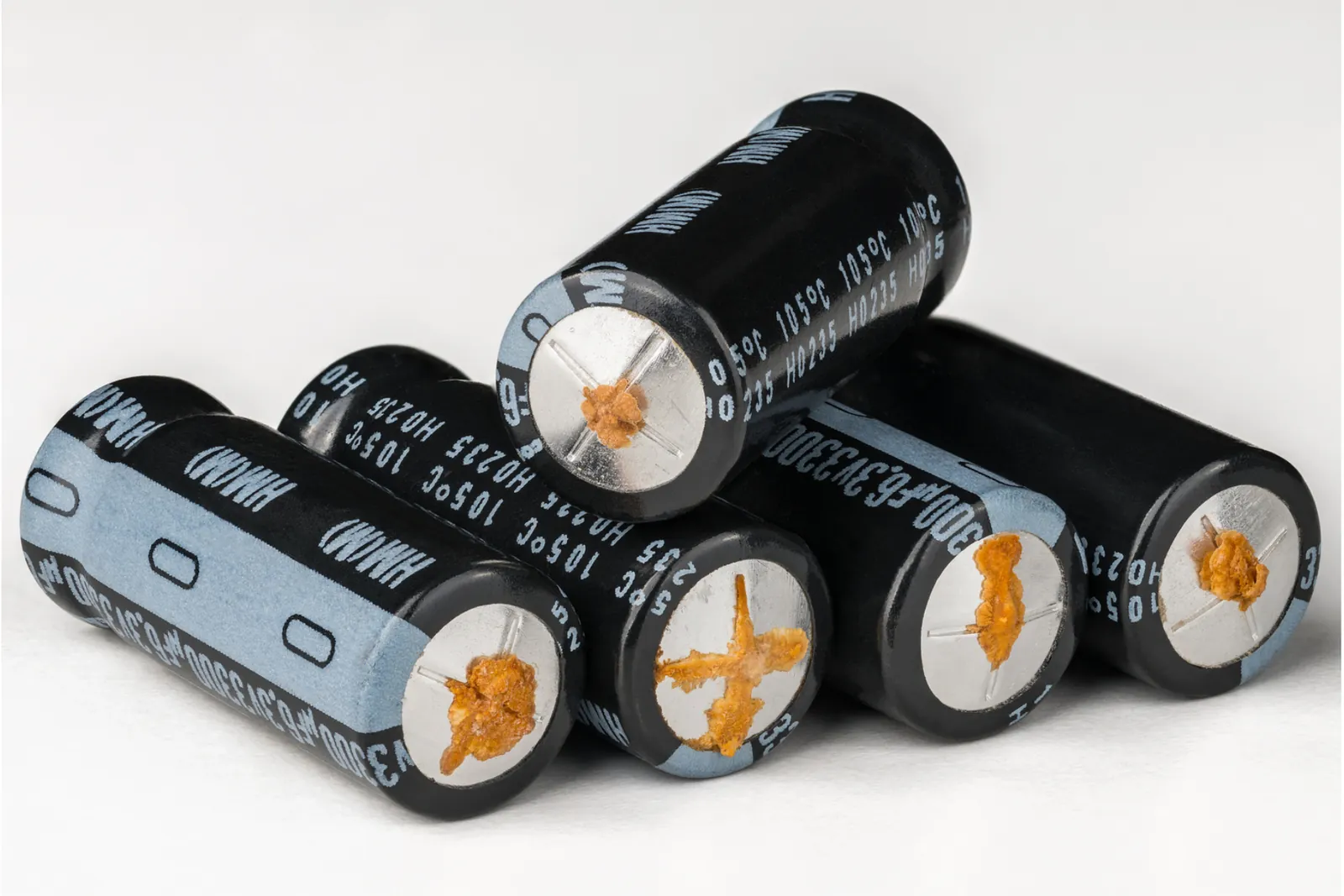
A swollen or domed top is the clearest sign. Manufacturers score the aluminum can with a cross or K-shape so it splits safely when internal pressure builds. If that vent bulges upward, the electrolyte is boiling and the part is dead.
Brown crust leaking from the bottom seal or the top vent means the liquid has escaped. That dried fluid corrodes copper traces and eats into the fiberglass board beneath it.
In a running circuit, excessive ripple voltage on the output tells you the capacitance has dropped. The power supply hums, screens flicker, or digital chips reset randomly because the filter isn’t smoothing the DC anymore.
When visual signs disagree with how the circuit behaves, an ESR meter settles it. It measures equivalent series resistance without removing the part from the board. A technician should perform this test to determine if the internal chemistry is degraded. Manufacturers like Nichicon publish expected lifespan formulas showing exactly how operating temperature increases that resistance over thousands of hours.
Errors that destroy electrolytic capacitors
- Ignoring the voltage derating rule. Running a 16 V part on a 15 V line leaves almost no margin for spikes, causing the dielectric to puncture during startup surges. Choose a voltage rating at least 20% higher than the highest steady voltage the circuit produces.
- Mixing up the polarity markings. The negative stripe points to ground, but some older schematics mark the positive side instead, leading builders to flip the part. Verify against the silkscreen on the actual board rather than trusting a faded diagram.
- Using a part rated for 85°C near a heatsink. Heat cuts the useful life in half for every 10°C rise above the rated temperature, turning a five-year part into a six-month failure. Always upgrade to 105°C or 125°C ratings when the component sits close to hot transistors or resistors.
- Storing unused stock for years. The oxide layer degrades without applied voltage, meaning a brand-new capacitor pulled from a decade-old drawer might draw heavy leakage current or pop instantly. Reform old stock slowly through a current-limiting resistor before putting it into a live circuit.
Frequently asked questions
Can I replace an electrolytic capacitor with a ceramic one?
No, you usually can’t swap them directly. Ceramic types don’t come in the large values, like 470 µF, that power supplies need for bulk storage. They also lack the equivalent series resistance that stabilizes certain voltage regulators. A technician should verify if the schematic specifically allows a change before you swap components.
Why do electrolytic capacitors bulge at the top?
They bulge because the internal electrolyte breaks down and produces hydrogen gas. The sealed aluminum can traps this gas until the pressure pushes the scored vent outward. This happens from age, excessive heat, or being installed backward in the circuit.
How long does an electrolytic capacitor last?
A standard part rated for 105°C typically lasts 2,000 to 10,000 hours at that maximum temperature. At cooler room temperatures, the lifespan extends dramatically, often lasting for a significant duration in consumer electronics. Check the manufacturer’s datasheet for the exact hour rating printed on your specific part.
Is it safe to touch a discharged electrolytic capacitor?
Yes, it’s safe to handle one after you’ve confirmed the voltage is zero. Large capacitors in power supplies store dangerous energy even when unplugged for days. Always measure across the terminals with a multimeter set to DC volts before touching the metal leads or the solder joints.
What happens if I put an electrolytic capacitor in backwards?
It will leak heavy current, heat up rapidly, and build internal gas pressure. Within seconds or minutes, the safety vent splits open, spraying corrosive electrolyte across the board. In larger power supply filters, reversing the polarity causes a loud explosion that destroys the component and scorches the surrounding area.
How many microfarads do I need for a 12V power supply?
There’s no single number, because the required capacitance depends on the current draw and acceptable ripple voltage. A small LED strip might need 100 µF, while a motor driver pulling a high current could require 2,200 µF or more. Calculate it using your load current and the ripple tolerance specified in your regulator’s datasheet.
Are tantalum capacitors better than aluminum ones?
Tantalum parts offer more capacitance in a smaller volume and hold their value better over time. However, they fail short-circuit rather than open, which can start fires if the supply lacks current limiting. Aluminum types remain the safer, cheaper choice for general power filtering where space isn’t extremely tight.
Conclusion
Every circuit relies on these parts to keep voltage steady, but they aren’t permanent fixtures. They dry out, leak, and lose their ability to filter noise as the years pass. Keeping spares matched to your board’s voltage and temperature needs saves you from chasing strange glitches later. Swap them cleanly, respect the stripe, and your equipment stays quiet and reliable.
