
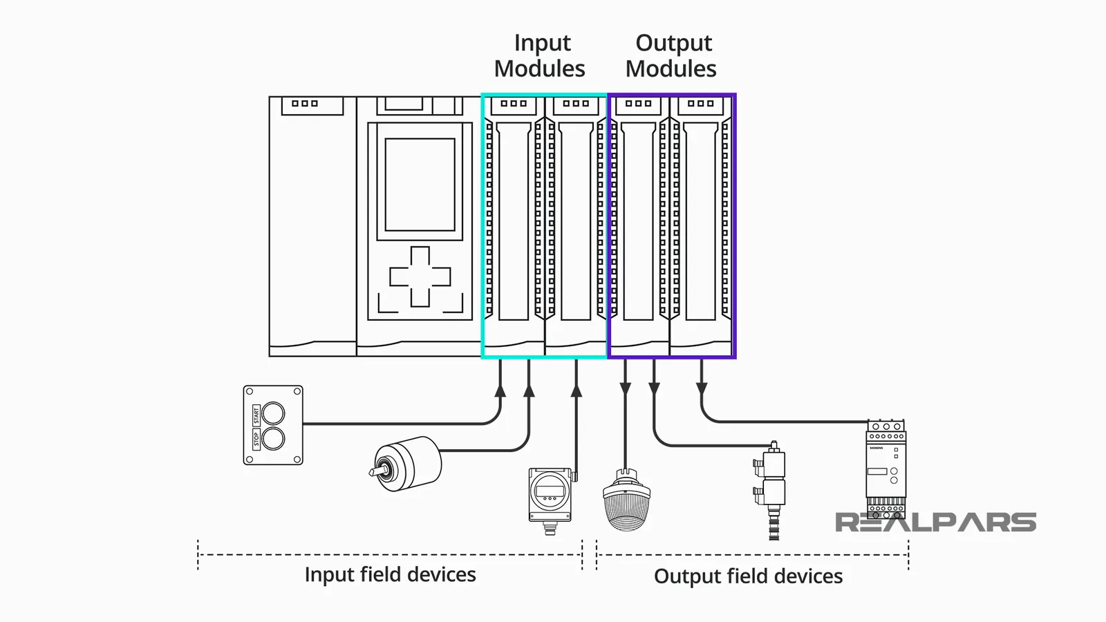
Programmable logic controller, or plc, outputs are the physical interfaces that allow a controller to send signals to external devices like motors, valves, and lights. Mastering signal types, current limits, and voltage ratings for these outputs is essential for safe automation system design.
These components vary based on the load type, the required switching speed, and the environment. You must account for the specific electrical characteristics of your hardware to prevent damage to the controller’s internal circuitry.
Understanding industrial control interfaces

Maintenance technicians, automation engineers, and students learning to build control panels often look for this information. This article serves those who need practical wiring guidance and safety thresholds. It assumes you have basic knowledge of DC and AC circuit principles. If you’re looking for programming logic or advanced communication protocols, those topics are outside the scope of this guide.
Factors that change the output performance
The choice of output card is the primary driver of system reliability. If your load is inductive, like a solenoid, you must use a flyback diode to suppress voltage spikes; if it’s purely resistive, like a heater, standard ratings apply.
Switching frequency matters greatly for performance. Solid-state outputs, such as transistors, can switch thousands of times per second, while mechanical relays are limited by the physical movement of metal contacts.
Current draw is the most common point of failure. If your device pulls more current than the output rating, the internal switch will fail. Always check the data sheet for the maximum continuous current per point and the total current per common group.
Voltage compatibility is also critical. An output designed for 24V DC won’t function with 120V AC, and applying the wrong voltage will destroy the module. Always verify the voltage label on the card itself before making any connections.
Wiring and testing procedures
- Disconnect all power sources to the controller and the field devices to prevent accidental short circuits.
- Verify the voltage rating of the output module matches the voltage of your field devices.
- Connect the common terminal of the output card to your power supply return path.
- Wire the positive side of your load to the specific output terminal, such as Q0.0 or O:0/1.
- Install a suppression device like a flyback diode across the load terminals if you’re using DC solenoids or relays.
- Reconnect power and check the status LED on the module when the logic state is set to high.
- Use a digital multimeter to measure the voltage across the load while the output is active to confirm the signal is present.
A job done properly shows a steady voltage match between the source and the load. If the voltage drops significantly when the device turns on, you likely have a loose connection or an overloaded circuit. Always stop if you notice smoke or burning smells and consult the manufacturer’s manual for your specific controller.
Comparison of output technologies
Different projects require different switching methods to balance speed, cost, and lifespan.
| Type | Best For | Max Speed | Lifespan |
|---|---|---|---|
| Relay | AC/DC high voltage | Slow | Limited cycles |
| Transistor | High speed DC | Very fast | Near infinite |
| Triac | AC loads | Medium | Very long |
Ensuring consistent system performance
Proper preparation
Experienced technicians always verify the load current against the module’s maximum rating before wiring. Beginners often ignore the total current limit for a group of outputs, which leads to overheating. Always group your high-current loads separately if the module allows it. Using wire ferrules ensures a solid connection that won’t vibrate loose over time, keeping signals clean and reliable.
Monitoring during operation
Watch the status LEDs on the module while the system runs. A flickering LED that should be solid often indicates a loose wire or a failing relay contact. Experienced users monitor the heat generated by the module during peak operation. If the module is too hot to touch, you’re likely pushing the current limits and should consider adding an external interposing relay.
Troubleshooting common output failures
| Observation | Likely Cause | First Step | Prevention |
|---|---|---|---|
| No signal output | Blown internal fuse | Check fuse status | Install external fuses |
| Flickering light | Loose connection | Tighten terminals | Use wire ferrules |
| Device stays on | Welded relay contact | Replace module | Use interposing relays |
| Signal is weak | Voltage drop | Clean connections | Check wire gauge |
Electrical safety and standards
Industrial automation follows strict safety protocols defined by the National Electrical Manufacturers Association (NEMA). You must ensure that your wiring methods comply with local codes, such as the NEC in the United States, which dictates how to separate control signals from high-voltage power lines.
Never exceed the maximum voltage or current ratings found on the module’s nameplate. If a module requires a specific grounding method, follow it exactly to prevent electromagnetic interference from triggering false signals. Always turn off the main breaker before attempting to replace a module to avoid electrical shock.
Real costs of system design
The cost of an output module is determined by the number of points and the type of switching hardware. High-density modules with 32 or 64 points save space but cost more and are harder to troubleshoot than 8-point modules. The real expense often lies in the external components, such as terminal blocks, DIN rail, and suppression devices.
If you choose a relay output module, budget for the eventual cost of replacement as mechanical parts wear out after millions of cycles. Always compare the cost of a replacement module against the cost of an external relay bank to decide which path is more economical for your specific installation.
Long term hardware maintenance
To keep your system running, perform an annual check on all terminal connections to ensure they remain tight. Dust buildup inside the cabinet can cause overheating, so use filtered air to clean the vents periodically. The primary sign that an output is failing is an intermittent signal or a relay that clicks but doesn’t pass current.
If you notice this, test the output with a multimeter while the load is disconnected. If the output still fails to switch, replace the module. Keeping a spare module on hand is the best way to reduce downtime during unexpected hardware failures.
Situations requiring alternative solutions
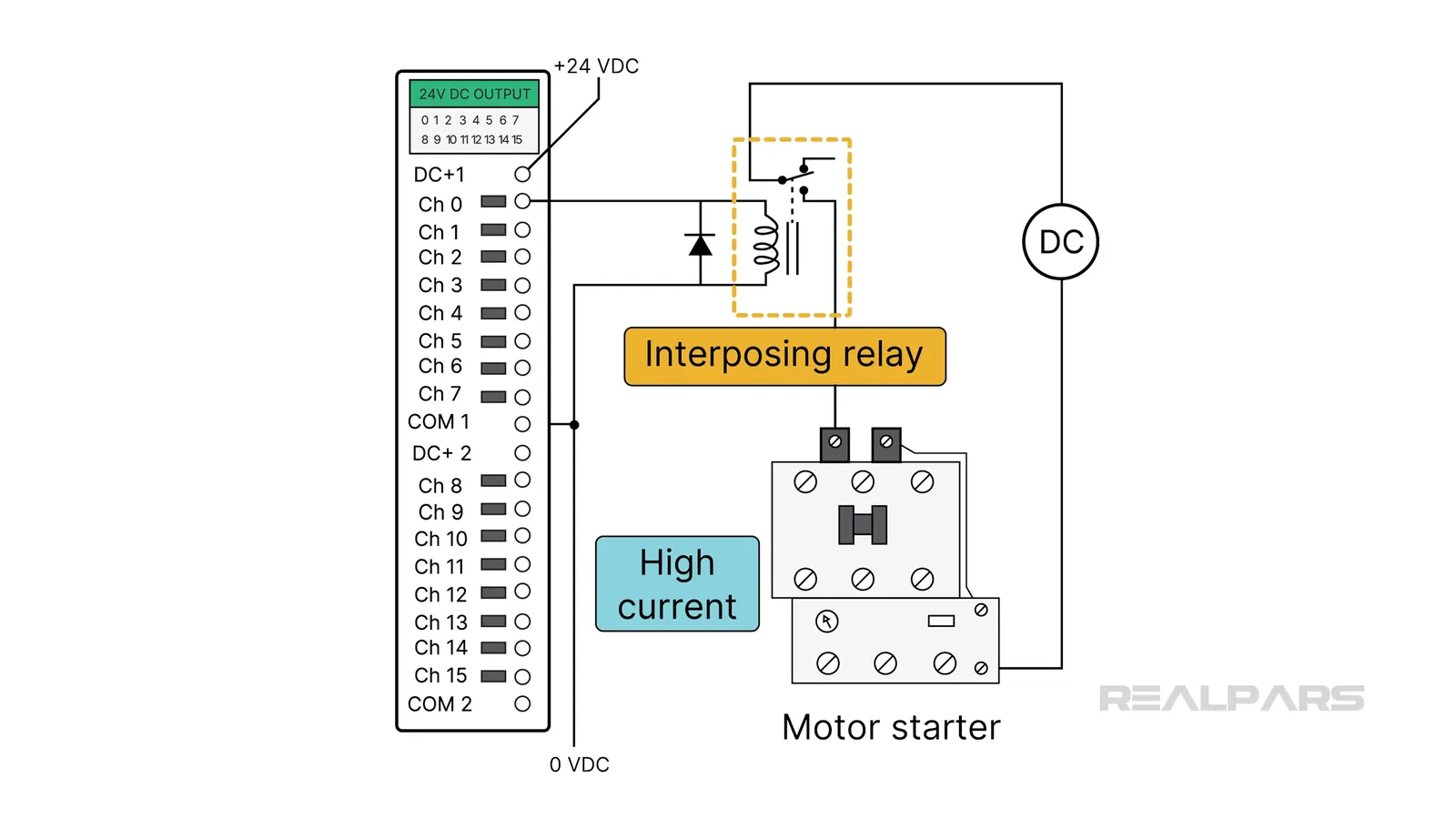
If you need to control high-power motors or large heaters, don’t connect them directly to the controller outputs. The current draw of these devices will instantly destroy the internal electronics. Instead, use the controller output to trigger an external contactor or motor starter.
If your application requires safety-rated stopping, use a dedicated safety PLC and certified safety outputs. These systems have internal diagnostics that verify the state of the output, which standard modules don’t provide. Always consult a certified electrical engineer if your system involves high-voltage power or safety-critical functions.
Frequently asked questions
Can I mix AC and DC loads on one card?
No, you can’t mix AC and DC loads on a single output card because the internal circuitry is designed for one specific voltage type and current path.
How often do relay outputs fail?
Relay outputs typically last between 100,000 and 1,000,000 cycles depending on the load current, as stated in the manufacturer’s technical specification document for your specific controller model.
Is it safe to wire an output directly to a motor?
No, you must never wire a motor directly to an output, as the high inrush current will cause the output to fail immediately; use an external contactor.
How do I identify the output current limit?
You identify the limit by reading the data sheet for your specific module part number, which lists the maximum current per point and the maximum total current per common.
What happens if I exceed the voltage rating?
Exceeding the voltage rating will result in immediate damage to the internal switching components, rendering the output point or the entire module permanently non-functional.
Does wire length affect output signals?
Yes, very long wire runs cause a voltage drop that can prevent the load from activating, so keep wiring runs short or use a higher gauge wire for distance.
Conclusion
Start by identifying the voltage and current requirements of your field device. Once you match these to the controller’s specifications, wire the device securely and test the signal with a multimeter. Stop immediately if you detect any unusual heat or electrical noise.
