
Integral control is a method used in automated systems to eliminate steady-state error by continuously adding up the difference between a target value and the current output over time. This process ensures that if a system is slightly off its goal, the controller keeps adjusting until the actual value matches the setpoint exactly. It acts like a memory that accounts for past errors to force the final result to zero.
The core idea is simple: if your system is currently below the target, the integral term adds more power to push it up. If it stays below the target for a long time, the integral term grows larger and larger, providing more force until the error is gone. It’s the part of a PID controller that removes the gap left by simpler, proportional-only systems.
Improving system precision
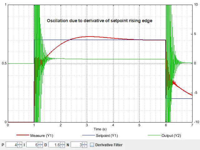
The most important thing to know is that integral control is about patience and long-term accuracy. If you try to make it work too fast, the system will overshoot the target and wobble back and forth. You must balance how much weight you give to the past errors versus how quickly you want the system to respond to new changes.
A common mistake is setting the integral time constant too low, which makes the system jumpy and unstable. People often think faster is always better, but in control loops, a very aggressive integral term causes the machine to “hunt” for the target. You should start with a conservative setting and only increase the influence of the integral term if the system fails to reach the exact target.
How integral control works
To set up an integral loop, you must define the time interval and the gain factor that tells the system how strongly to react to accumulated errors. Follow these steps to ensure your system stabilizes without constant oscillation.
- Set your proportional gain first to get the system close to the target, as the integral term should only handle the final, small gap.
- Calculate the integral time constant by observing how long it takes for your system to reach the target after a disturbance.
- Introduce the integral gain slowly, starting at a very low value, to see if the steady-state error decreases.
- Monitor the response curve; if you see the output bouncing above and below the target, reduce the integral gain immediately.
- Check for windup, which happens when the error accumulates while the system is physically unable to reach the target, such as a valve that’s already fully open.
- Use an anti-windup circuit or a limit on the integral output to stop the error from growing when the system is saturated.
Tip: If your system is a simple heating element, a long integral time is fine because temperature changes slowly. Tip: For high-speed motion control, you need a very short integral time, or the machine will lag behind the command.
Timing and system performance
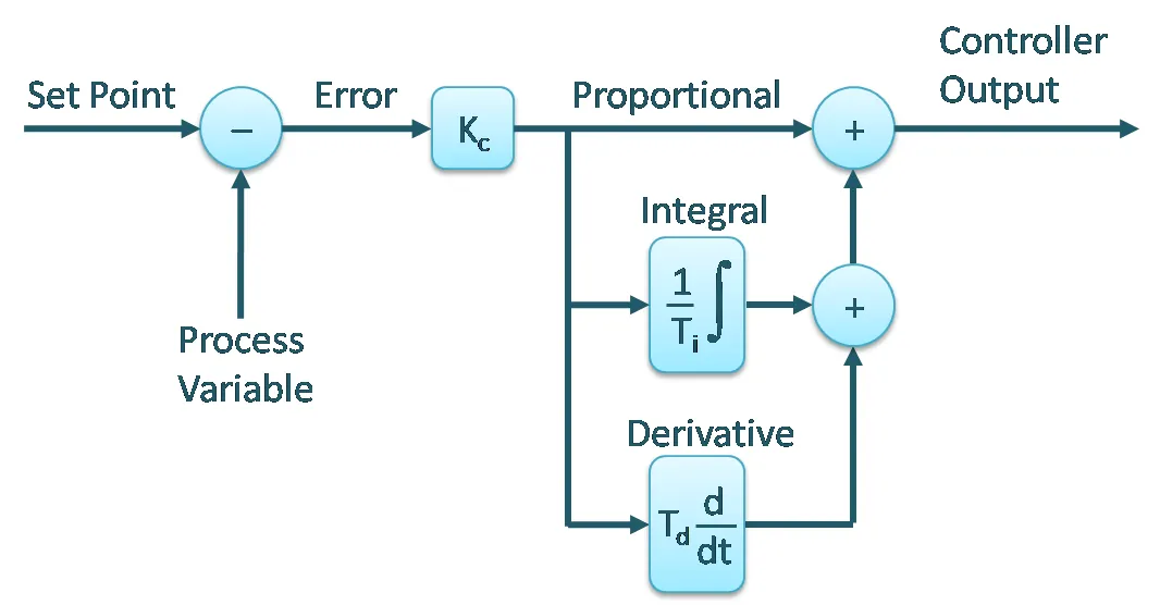
The time it takes to settle depends on the physical nature of your hardware and the size of the load you’re controlling. You can find the specific timing requirements for your application by reviewing the PID controller technical guidance provided by international standards bodies for industrial process control.
| System Type | Typical Response Time | Sensitivity | Main Risk |
|---|---|---|---|
| Temperature Control | 30–120 seconds | Low | Overshoot |
| Pressure Regulation | 1–5 seconds | Medium | Instability |
| Motor Speed Control | 0.1–0.5 seconds | High | Oscillation |
| Liquid Level Control | 10–60 seconds | Low | Windup |
If your system takes much longer to settle than these ranges suggest, check your sensor for noise or latency. A delayed reading forces the integral term to react to old data, which ruins the stability of the entire loop.
Checking for steady state
You know the controller is working when the output stays locked on the target value even when the system faces small, constant resistance. Watch the sensor data on your controller interface; if the graph shows the value hovering tightly around the setpoint without drifting away, the integral term is doing its job.
The ultimate test is applying a small, steady load to the system. If the controller increases power to compensate and keeps the target steady, the integral logic is correct.
If you see the value oscillating above and below the target, your integral gain is likely set too high. Dial it back by 20 percent increments until the hunting stops. Conversely, if the system settles at a value consistently lower than your target, your integral term is too weak to overcome the resistance. Increase the gain until the offset vanishes. Always test for at least three full cycles.
Common tuning errors
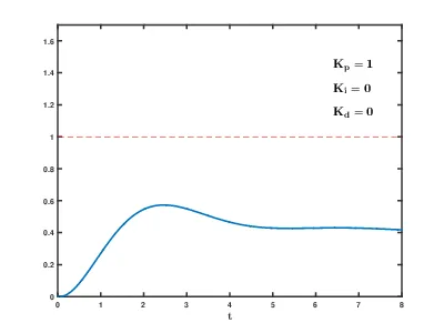
- Excessive integral gain: This causes the system to over-correct, leading to continuous, widening swings around the target. Always lower the gain until the oscillations stop, then increase it only by small increments.
- Ignoring sensor noise: If your sensor gives shaky readings, the integral term adds up all that noise, which makes the output jittery and unreliable. Use a low-pass filter on your sensor input to smooth the signal before it reaches the controller.
- Failing to limit output: When the system hits a physical wall, like a pump at 100% power, the integral term keeps adding up the error in the background. This “windup” makes the system stay at full power much longer than necessary, which causes a massive overshoot once the target is finally reached.
Frequently asked questions
Is integral control always necessary?
No, it isn’t always needed if your system can tolerate a small, constant gap between the target and the actual result. Many simple systems, like basic thermostats, use only proportional control because they don’t require perfect precision. You should only add integral control if your process requires the output to match the setpoint exactly every time, regardless of external loads or resistance.
How do I stop integral windup?
You stop windup by limiting the maximum value the integral term can reach or by freezing the integration when the controller hits its physical limit. This prevents the “memory” of the error from growing uncontrollably when the machine is already working as hard as it can. Most modern digital controllers have an “anti-windup” setting you can enable to handle this automatically without extra hardware.
Why does my system oscillate?
Your system oscillates because the integral gain is set too high, causing the controller to over-react to the accumulated error. Every time the output crosses the target, the integral term has already “remembered” too much error and pushes the system too far in the opposite direction. You should decrease the integral gain until the output settles smoothly onto the target without crossing it more than once.
Can integral control work alone?
No, it can’t work well on its own because it’s too slow to react to sudden changes and usually leads to instability. It’s designed to work as part of a PID loop, where the proportional term handles the fast movement and the integral term handles the final precision. Using only an integral controller would make your system extremely sluggish and prone to massive overshoots during any startup or change.
How long should the integral time be?
The integral time should be set based on the natural response speed of your equipment, usually starting at a value equal to the system’s “time constant.” You can find this by measuring how long the system takes to reach 63% of its final value after a step change. For most industrial heating or fluid systems, this ranges from a few seconds to a couple of minutes depending on the mass involved.
Is it safe to tune while running?
It’s safe to tune if you make very small adjustments and monitor the output constantly, but you must be prepared to stop the process if the system becomes unstable. Never make large changes to the gain values while the machine is under a heavy load or working with hazardous materials. If you aren’t sure how the system will react, always perform your tuning on a dry run without active output.
Conclusion
You’ll find that balancing this method with proportional and derivative settings creates the most stable performance. It’s a powerful tool, but don’t worry if your initial tuning feels a bit tricky. Try experimenting with different gain values in a simple simulation; you’ll quickly see how these adjustments improve your system’s overall accuracy.
