
A cam and follower mechanism converts rotational motion into linear or oscillating motion by utilizing a specially shaped surface to push against a contact point. This fundamental assembly serves as the mechanical heart of countless devices, from the internal combustion engines powering our vehicles to the intricate timing systems found in vintage mechanical watches. By carefully designing the profile of the rotating cam, engineers can dictate the precise timing, speed, and distance of the follower’s movement, allowing for highly complex sequences of operations within a compact footprint.
Key Takeaways
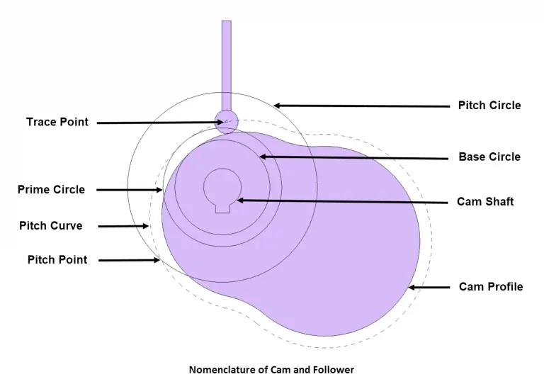
- Use a knife-edge follower for simple, low-load applications where space is highly constrained.
- Select a roller follower to minimize friction and wear during high-speed, heavy-duty mechanical operations.
- Ensure the cam profile is calculated precisely to prevent “follower bounce” at high rotational velocities.
- Incorporate lubrication channels to extend the service life of both the cam and the follower contact surfaces.
- Verify the pressure angle remains within safe limits to prevent the mechanism from jamming or locking up.
How Does a Cam Mechanism Work?
At its core, the mechanism consists of two primary components: the cam, which acts as the driver, and the follower, which acts as the output. As the cam rotates about its axis, its irregular or eccentric surface forces the follower to move in a specific, repeatable pattern. The shape of the cam is the primary determinant of the follower’s displacement, velocity, and acceleration.
The interaction between these two parts relies on the constant contact maintained between the cam profile and the follower head. This contact is typically enforced by external forces, such as a return spring or the weight of the follower assembly itself.
When the cam turns, the follower is pushed outward during the “rise” phase, held steady during the “dwell” phase, and allowed to retract during the “fall” phase. This sequence is perfectly synchronized with the angular position of the camshaft, ensuring that operations occur at the exact moment required by the machine’s overall design.
Different Types of Followers
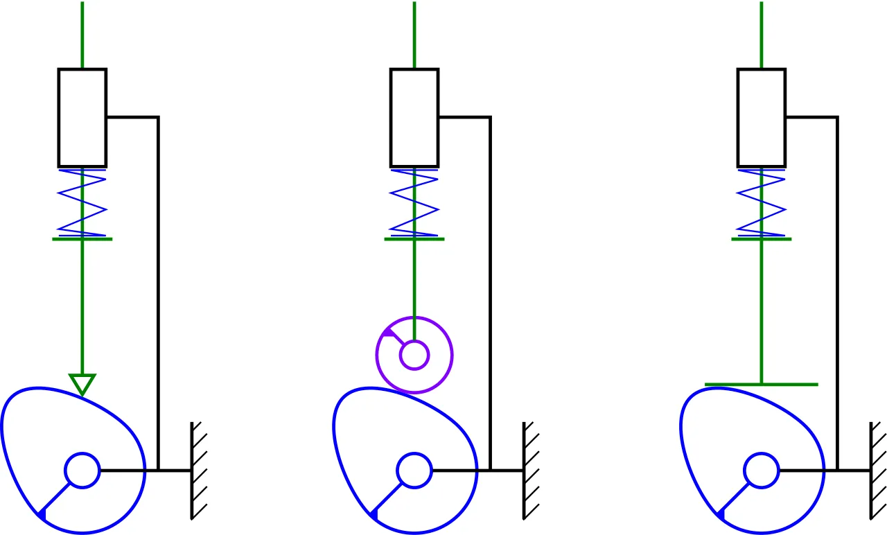
The interface between the cam and the follower is a critical friction point. Choosing the right geometry helps manage mechanical stress and ensures smooth operation.
| Follower Type | Primary Advantage | Best Application |
|---|---|---|
| Knife-Edge | Compact design | Low-speed, light-duty |
| Roller | Minimal friction/wear | High-speed, heavy-duty |
| Flat-Faced | Can handle high side loads | Compact valve trains |
| Spherical | Accommodates misalignment | General purpose assembly |
Mechanical efficiency is heavily dependent on the contact geometry. A roller follower, for instance, replaces sliding friction with rolling friction, which significantly reduces heat generation and material degradation. Conversely, a flat-faced follower is often preferred in automotive engines because it can sustain high vertical pressure without the risk of the roller bearing seizing under extreme heat or load conditions.
Analyzing Cam Profile Design
The geometry of the cam is rarely a simple circle. Engineers use specific mathematical curves—such as cycloidal, harmonic, or polynomial profiles—to determine how the follower moves. These profiles are designed to control the jerk characteristics of the system. If the acceleration changes too abruptly, the mechanism will vibrate, creating noise and potentially causing the follower to lose contact with the cam surface.
Selecting the Correct Motion
- Simple Harmonic Motion: Provides smooth transitions, ideal for moderate speeds.
- Cycloidal Motion: Offers the best acceleration characteristics, minimizing vibration at high rotational speeds.
- Constant Velocity: Used when the follower must move at a steady rate over a specific distance.
Why Does Mechanical Timing Matter?
In any automated system, timing is everything. The cam and follower mechanism provides a “mechanical memory” that guarantees events happen in the correct sequence without the need for complex electronic sensors. For example, in an engine, the camshaft ensures that intake and exhaust valves open and close at the exact millisecond the piston reaches the correct position.
Synchronization accuracy is achieved by indexing the cam to the primary drive shaft. If the timing slips even by a few degrees, the entire system can fail, leading to catastrophic damage in high-performance machinery. This is why timing belts and chains are used to lock the rotational position of the cam relative to the crankshaft.
Troubleshooting Common Mechanism Issues
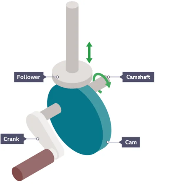
Even the most robust systems encounter problems over time. Most issues stem from improper maintenance or the degradation of the contact interface.
| Symptom | Potential Cause | Suggested Fix |
|---|---|---|
| Excessive Noise | Lack of lubrication | Apply high-pressure grease |
| Erratic Movement | Follower spring fatigue | Replace return springs |
| Surface Pitting | High contact stress | Redesign profile radius |
| Binding/Sticking | Misaligned follower | Check guide rail tolerances |
Preventative maintenance involves regular inspection of the contact surfaces. If you see signs of “spalling” or metal flaking on the cam, the material has reached its fatigue limit and the component must be replaced.
Frequently Asked Questions
What is a dwell period?
A dwell period occurs when the follower remains stationary while the cam continues to rotate. This happens when the cam profile is perfectly circular at a specific radius relative to the pivot point. It’s essential for allowing other machine operations, such as clamping or welding, to occur while the follower is held in a fixed position.
Why do some cams use springs?
Springs are necessary to ensure the follower maintains contact with the cam profile during the “fall” phase. Without a spring or a positive return mechanism, the follower might lose contact due to gravity or inertia, leading to erratic movement, loud rattling, or mechanical failure. The spring acts as a constant force, pushing the follower back against the cam surface at all times.
What is the pressure angle?
The pressure angle is the angle between the direction of the follower’s motion and the normal to the cam profile at the point of contact. If this angle becomes too steep, the force required to move the follower increases significantly, and the system may jam. Engineers must keep this angle within specific limits to ensure the mechanism operates smoothly without excessive mechanical strain.
Can cams move in two directions?
Standard cam mechanisms are designed for one-way rotation. However, some specialized designs, known as conjugate cams or groove cams, feature a track that forces the follower to move in both directions without relying on a spring. These are used in high-precision robotics or textile machinery where the follower must follow an exact path regardless of external forces or speed.
How do I reduce wear on cams?
To minimize wear, ensure the cam and follower are made from compatible, hardened materials, such as case-hardened steel. Proper lubrication is vital; using a high-viscosity lubricant helps create a thin film between the surfaces, preventing metal-to-metal contact. Additionally, ensure the follower is perfectly aligned with the cam axis to prevent uneven loading that leads to premature localized wear or surface fatigue.
Conclusion
For those looking to deepen their mechanical expertise, consider studying the kinematics of machinery to better understand how different cam shapes influence output motion. You can start by drafting your own cam profiles using CAD software to simulate how different radii affect the rise and fall timing of your follower. Once you have a working model, test it in a small-scale prototype before committing to full-scale fabrication.
