
Isolator switches fail primarily due to mechanical wear, electrical arcing, and environmental corrosion that degrade internal contacts over time. These failures often manifest as intermittent power loss, visible scorching, or a complete inability to disconnect the circuit safely. Understanding the specific root causes allows homeowners and electricians to diagnose issues accurately before they escalate into hazardous electrical faults or fire risks.
Key Takeaways
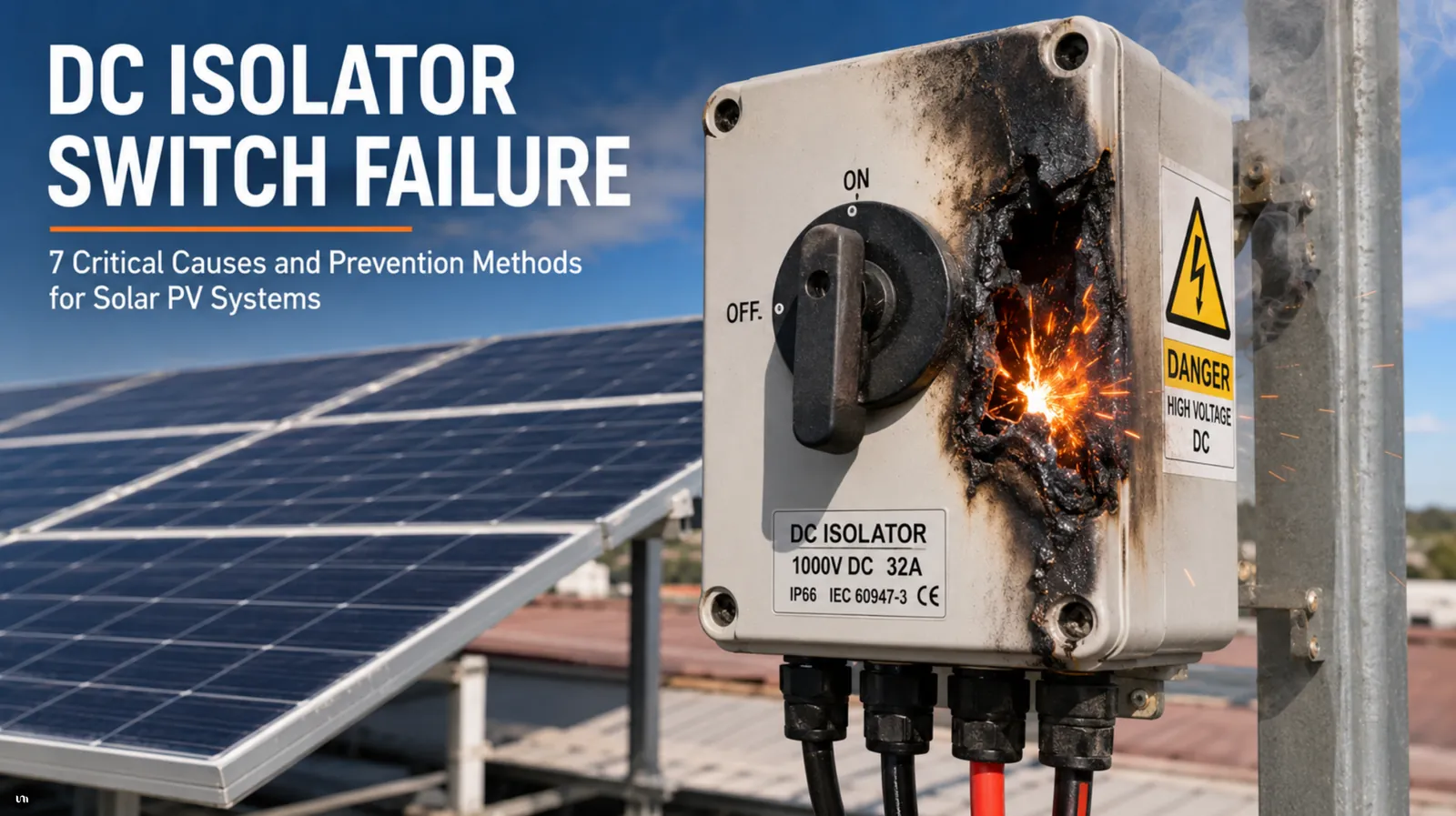
- Regular visual inspections can identify early signs of thermal damage, such as discoloration or melting on the switch housing.
- Moisture ingress is a leading cause of failure in outdoor isolators, requiring strict adherence to IP rating standards.
- Overloading circuits beyond the switch’s rated amperage accelerates contact erosion and increases the risk of catastrophic failure.
- Professional replacement is mandatory for failed isolators, as attempting repairs on live high-voltage components poses severe safety hazards.
- Correct torque settings during installation prevent loose connections that generate heat and lead to premature component degradation.
Mechanical Wear and Tear
Isolator switches are electromechanical devices designed for infrequent operation, meaning their internal mechanisms aren’t built for daily cycling like standard light switches. The primary point of failure is often the spring-loaded mechanism that ensures rapid contact separation. Over years of use, these springs can lose tension, causing the contacts to open slowly. Slow separation leads to sustained arcing, which vaporizes metal from the contact surfaces. This pitting increases electrical resistance, generating excessive heat during normal operation.
Another common mechanical issue involves the operating handle linkage. Plastic components within the handle assembly can become brittle due to age or UV exposure if located near windows or outdoors. When these parts crack, the handle may feel loose or fail to engage the internal contacts fully. A partially engaged switch creates a high-resistance path, resulting in significant voltage drop and heat buildup. This heat further degrades surrounding insulation, creating a cascading failure mode that compromises the entire unit’s integrity.
Electrical Arcing Damage
Electrical arcing occurs when current jumps across a gap between separating contacts. While isolators are designed to minimize this, repeated operation or switching under load can cause significant damage. The intense heat from an arc, which can exceed several thousand degrees Celsius, melts and oxidizes the contact material.
Most quality isolators use silver-alloy contacts for their conductivity and resistance to welding, but even these degrade over time. Contact erosion reduces the surface area available for current flow, increasing resistance and temperature.
Warning: Never operate an isolator switch under heavy load unless it’s specifically rated for on-load switching. Doing so creates massive arcs that can weld contacts together or shatter the housing.
The resulting carbon deposits from arcing act as insulators, preventing proper electrical connection even when the switch appears closed. This leads to intermittent power supply issues that are difficult to diagnose without opening the unit. In severe cases, the arc can ionize the air inside the enclosure, creating a conductive path that causes a short circuit between phases or to earth. This scenario often results in immediate tripping of upstream protective devices or, worse, an electrical fire if protection fails.
Environmental Corrosion Effects
Environmental factors play a critical role in the longevity of isolator switches, particularly those installed in harsh locations. Moisture ingress is the most destructive element, causing oxidation of copper and brass components.
Even minor condensation inside the enclosure can lead to green verdigris formation on terminals, which acts as an insulator and increases contact resistance. For outdoor installations, the Ingress Protection (IP) rating is vital. An IP65-rated switch is protected against dust and low-pressure water jets, while lower ratings offer insufficient protection for exposed areas.
Salt spray in coastal environments accelerates corrosion significantly, attacking metal parts and degrading plastic housings. UV radiation from sunlight also breaks down polymer chains in the switch casing, making it brittle and prone to cracking. Once cracks form, water and debris enter freely, compromising the dielectric strength of the enclosure. Regular maintenance should include checking seal integrity and applying appropriate dielectric grease to terminals to repel moisture and prevent oxidation.
Thermal Stress and Overloading
Heat is both a symptom and a cause of isolator switch failure. When a switch operates near its maximum current rating, resistive heating occurs at the contacts and terminals.
If the connections aren’t tightened to the manufacturer’s specified torque settings, microscopic gaps exist between the wire and the terminal. These gaps create high-resistance points that generate localized hot spots. Over time, this heat cycles the metal, causing it to expand and contract, which further loosens the connection in a process known as thermal cycling.
| Failure Symptom | Likely Cause | Immediate Action |
|---|---|---|
| Discolored housing | Excessive heat generation | Turn off power and inspect terminals |
| Burning smell | Insulation melting | Evacuate area and call electrician |
| Humming noise | Loose laminations or arcs | Schedule immediate professional inspection |
| Hot to touch | High resistance connection | Don’t touch; isolate circuit immediately |
Continuous overheating degrades the insulation materials surrounding the conductors, potentially leading to short circuits. In extreme cases, the heat can melt the plastic housing, exposing live parts and creating a shock hazard. Ensuring that the isolator is correctly sized for the load it controls is essential. Using a 32-amp switch for a 40-amp shower, for example, will inevitably lead to premature failure due to constant thermal stress.
Installation Errors and Misuse
Many isolator failures stem from incorrect installation rather than manufacturing defects. One common error is using the wrong type of cable or failing to strip the insulation properly, leaving strands frayed or insufficiently clamped. Another frequent mistake is ignoring the minimum bending radius of cables, which puts mechanical stress on the terminals. This stress can pull wires loose over time, especially in vibrations-prone areas like near washing machines or industrial equipment.
Misuse also contributes to failure. Isolators are intended for isolation during maintenance, not as routine on/off switches for daily appliances. Frequent operation wears out the mechanical components faster than designed. Additionally, some users attempt to bypass safety interlocks or modify the switch to accept larger cables than rated, compromising the enclosure’s integrity. Proper training and adherence to wiring regulations, such as the NEC Article 110 requirements, ensure that installations remain safe and durable over their intended lifespan.
How to Diagnose a Failing Switch
Listen for unusual noises such as buzzing or crackling, which signal arcing or loose components. Test the mechanical action of the handle; it should move smoothly and snap firmly into position. Any stiffness or looseness suggests internal mechanical wear. If the switch trips upstream breakers when operated, it likely has internal shorting due to carbon tracking or moisture. Always de-energize the circuit before removing the cover for internal inspection, and verify zero energy with a tested voltage detector.
Preventive Maintenance Strategies
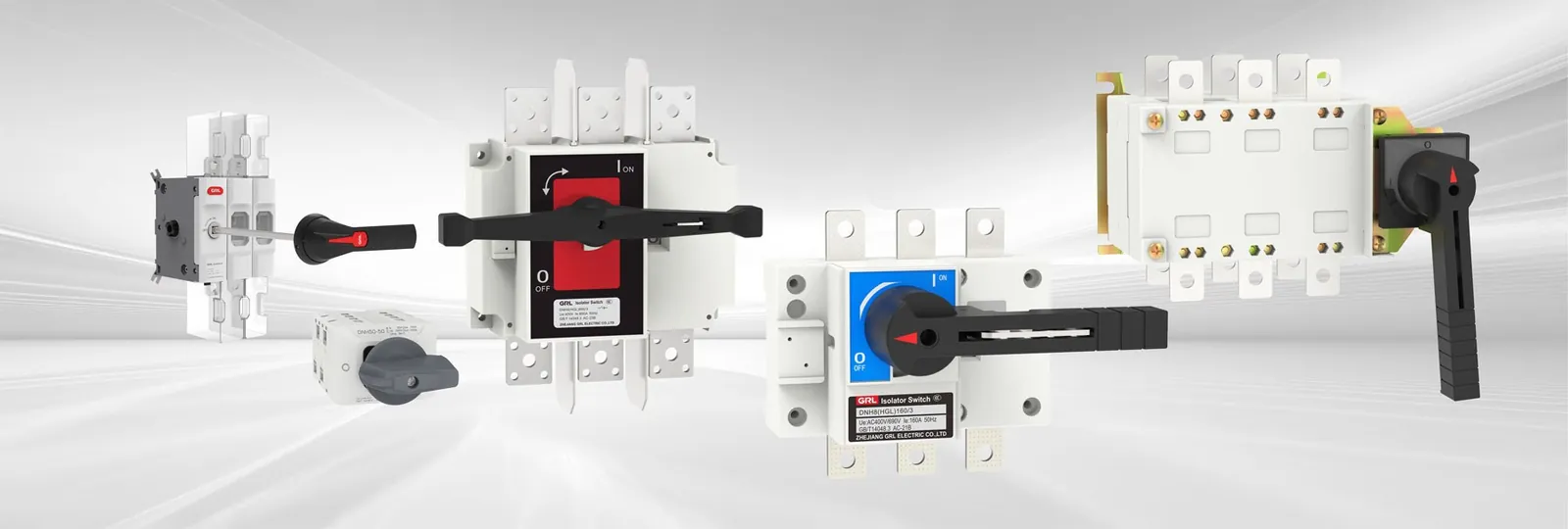
Preventive maintenance extends the life of isolator switches and ensures reliable operation. Schedule annual inspections for critical circuits, focusing on tightness of terminal connections and condition of insulation. Clean external surfaces with a dry cloth to remove dust and debris that can trap moisture. For outdoor units, check seals and gaskets for deterioration and replace them if necessary. Apply a thin layer of dielectric grease to exposed metal terminals during reassembly to prevent corrosion.
Avoid switching the isolator under load whenever possible. Turn off the appliance or downstream breaker first, then operate the isolator. This practice minimizes arcing and reduces mechanical stress on the contacts. Keep the area around the switch clear of obstructions to allow for adequate ventilation and heat dissipation. Record maintenance activities and any observed anomalies to track the health of the installation over time. Proactive care prevents unexpected failures and enhances overall electrical safety.
Related guides
- Maytag MVWC565FW1 Problems: How to Fix Common Washer Issues
- Maytag Refrigerator Troubleshooting: Fix Cooling and Noise Issues
- Verizon Fios Router Blinking White: How to Fix Your Connection
Frequently Asked Questions
Can I repair a broken isolator switch?
No, isolator switches should never be repaired. They’re sealed units designed for replacement, not repair. Attempting to fix internal contacts or mechanisms compromises safety certifications and creates significant shock and fire hazards. Always replace a faulty isolator with a new, compliant unit installed by a qualified electrician to ensure system integrity.
How often should isolator switches be replaced?
There’s no fixed lifespan, but most manufacturers recommend inspection every five years. Replacement is necessary if signs of wear, overheating, or mechanical failure appear. In harsh environments like coastal or industrial areas, more frequent checks are advisable. Proactive replacement after ten to fifteen years can prevent unexpected failures in critical circuits.
Why does my isolator switch feel hot?
A hot isolator indicates high electrical resistance, usually from loose terminals or corroded contacts. This resistance generates heat as current flows through the restriction. It’s a serious warning sign of potential fire risk. Immediately turn off the power and have a professional inspect and tighten connections or replace the unit to prevent further damage.
What IP rating do I need for outdoor isolators?
For outdoor installations, a minimum of IP65 is recommended. This rating ensures protection against dust ingress and low-pressure water jets from any direction. In areas with heavy rain or hose-down cleaning, IP66 or IP67 provides better protection. Always check local regulations and manufacturer guidelines for specific environmental requirements to ensure long-term reliability.
Is it safe to use an isolator as a daily switch?
No, isolators aren’t designed for frequent operation. They lack the arc chutes and durable contacts found in regular switches. Daily use accelerates mechanical wear and electrical erosion, leading to premature failure. Use a dedicated control switch for daily operations and reserve the isolator for maintenance isolation only to extend its service life and maintain safety.
Conclusion
Understanding why isolator switches fail empowers you to maintain a safer electrical environment. By recognizing the signs of mechanical wear, arcing, and environmental damage, you can take proactive steps to prevent hazardous situations. Regular inspections and correct usage are key to longevity. If you suspect any issues with your isolator, consult a licensed electrician immediately to assess and replace the unit if necessary.
