
Roundness is a geometric property that describes how closely the cross-section of a cylindrical or spherical object approaches an ideal circle. In manufacturing and quality control, this measurement is critical because components that deviate from perfect geometry—often due to vibration, tool wear, or thermal expansion—can cause premature mechanical failure or excessive noise in high-precision assemblies. Measuring this property requires capturing the variations in radius along the part’s perimeter relative to a common center point.
Key Takeaways
- Roundness is defined as the difference between two concentric circles that enclose the actual profile of the part.
- Always use a fixed-spindle gauge or a rotating-table instrument to eliminate alignment errors during testing.
- Filter settings are essential when measuring; you must decide whether to measure long-wave “lobing” or short-wave surface roughness.
- Maintain a stable environment with controlled temperature, as thermal expansion can easily skew sub-micron measurements.
- Standardize your calibration artifacts, such as high-precision glass hemispheres, to ensure your measurement system remains accurate over time.
Defining Roundness and Its Significance
At its core, roundness is a two-dimensional geometric tolerance. It specifies that all points on the surface of a circular feature must lie within a radial distance of a specific value. Engineers use this metric to ensure that bearings, pistons, and shafts fit correctly within their housings. When a part is not “round,” it exhibits variations known as out-of-roundness, which are often characterized by lobes or peaks that disrupt the function of the assembly.
A deviation from perfect roundness creates uneven load distribution. For example, in a high-speed motor, an oval-shaped shaft will generate vibration, leading to heat buildup and eventual bearing seizure. By quantifying roundness, manufacturers can identify if their CNC machines are suffering from spindle runout or if the material itself is warping during the heat-treatment process.
How Is Roundness Measured?
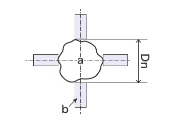
Measuring roundness isn’t as simple as taking a diameter measurement with calipers. Calipers or micrometers can only measure the distance between two opposite points, which fails to detect odd-numbered lobes—a common defect where the diameter remains constant even though the shape isn’t a circle. True roundness measurement requires a rotational reference to map the entire perimeter of the part.
The Minimum Zone Method
The most common mathematical approach is the Minimum Zone Center (MZC). This method calculates the distance between two concentric circles that contain the entire profile of the part while minimizing the radial difference between them. This is the standard definition established by the International Organization for Standardization for geometric tolerancing.
Common Measurement Instruments
| Instrument Type | Best For | Typical Accuracy Range |
|---|---|---|
| Handheld Dial Gauge | Rough shop-floor checks | 0.010 mm – 0.050 mm |
| Bench Center Gauge | Mid-range production parts | 0.005 mm – 0.020 mm |
| Rotating Table System | Ultra-precision components | 0.0001 mm – 0.002 mm |
Step-by-Step Measurement Procedure
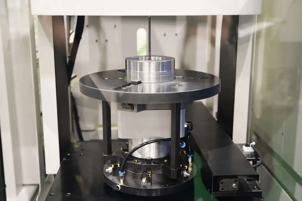
To achieve reliable results, follow a structured workflow that accounts for both the part and the machine. Consistency is the primary goal when attempting to minimize measurement uncertainty.
- Clean the component: Remove all oil, burrs, and particulate matter, as even a small speck of dust can be interpreted as a significant geometric error.
- Align the axis: Place the part on the rotating table and adjust the leveling stage. The axis of the part must be perfectly aligned with the axis of the rotation of the gauge.
- Select the filter: Choose the appropriate filter setting (often measured in undulations per revolution, or UPR). This determines which surface features are included in your final roundness value.
- Perform the rotation: Rotate the part for 360 degrees while the stylus maintains light, constant contact with the surface.
- Analyze the plot: Use the software to output the radial deviation graph, which will visually highlight the peaks and valleys of the profile.
What Causes Roundness Errors?
Understanding the root cause of a defect is just as important as measuring it. Most errors stem from the manufacturing process itself. Workpiece deflection occurs when the tool exerts too much pressure on a thin-walled part, causing it to deform during cutting. Another frequent culprit is machine vibration, which translates into a wavy surface finish that prevents the part from achieving a true circular cross-section.
- Thermal distortion: Heat generated by friction causes the metal to expand unevenly.
- Chuck pressure: Clamping a part too tightly in a lathe or mill can “pinch” the material, creating a multi-lobed shape.
- Tool wear: A dull cutting edge will push against the material rather than slicing it, leading to irregular surface profiles.
- Unstable fixtures: If the part isn’t held securely, it will shift slightly during the machining operation.
Choosing the Right Equipment
When selecting a measurement device, consider your tolerance requirements. If you’re manufacturing standard industrial bolts, an entry-level gauge is sufficient. If you’re working in the aerospace or semiconductor sectors, you’ll need a high-end roundness tester equipped with an air-bearing spindle.
Warning: Never attempt to measure roundness by rotating the part by hand; the human touch introduces irregular pressure and speed, which will result in data that’s practically useless for quality control.
Evaluating Surface Filters
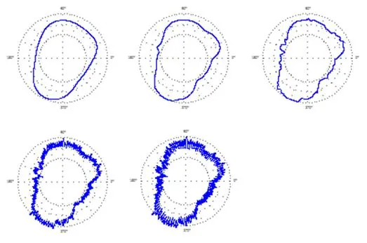
Data filtering is the most misunderstood aspect of roundness measurement. A raw measurement will include everything from the shape of the part to the microscopic texture of the metal. By applying a Gaussian filter, you can isolate the specific wavelengths you need to analyze. For instance, if you’re looking for structural lobing, you might set the filter to 50 UPR, effectively ignoring the surface roughness that could otherwise mask the underlying geometric error.
Frequently Asked Questions
Is roundness the same as circularity?
Yes, in the field of Geometric Dimensioning and Tolerancing (GD&T), roundness and circularity are synonymous. Both terms refer to the same geometric control where a circular feature must be contained within two concentric circles separated by a specific distance. Engineers use these terms interchangeably to describe the control of a cross-section, though “roundness” is more common in shop-floor parlance while “circularity” is the formal term used in engineering drawings.
What is the difference between roundness and runout?
Roundness measures the shape of the part in isolation. Runout, however, measures how the part behaves in relation to its axis of rotation. A part can have perfect roundness but still have high runout if it’s mounted off-center. Conversely, a part could theoretically have low runout while being significantly out-of-round, depending on how it’s held and measured during the inspection process.
Can I measure roundness with a micrometer?
No, a micrometer is unsuitable for measuring roundness. Because a micrometer only measures the diameter between two points, it can’t detect “even-lobed” errors, such as a triangle-shaped hole or a square-shaped shaft. These shapes can have a constant diameter, leading a micrometer to show a “perfect” reading even when the part is severely distorted. You must use a rotational gauge to detect such geometric defects.
Why does temperature affect roundness?
Metal expands and contracts with temperature changes. If your measurement room isn’t climate-controlled, the part may change shape while it’s being measured, or the internal components of the measurement gauge may shift due to thermal drift. To ensure accuracy, the inspection area should be kept at a stable 20 degrees Celsius, and parts should be allowed to reach thermal equilibrium before testing begins.
What is the most accurate way to measure?
The most accurate method involves using a high-precision, air-bearing spindle roundness tester. These machines use a precision-ground reference axis that’s independent of the part’s rotation. By using a highly sensitive electronic probe that records thousands of data points per revolution, these systems can distinguish between true shape errors and random noise, providing a level of precision down to the sub-micron level for critical industrial components.
Pro Tip: Always verify your measurement system by testing a standard reference sphere before starting a shift to ensure the probe sensitivity and the machine alignment are within the manufacturer’s specified tolerances.
Conclusion
If you’re looking to improve your quality control processes, your next step should be to assess the specific tolerance requirements of your parts and determine whether your current shop-floor equipment meets those needs or if you must transition to a dedicated rotational gauge for higher accuracy and traceability.
